Form No. 3386-896 Rev A Pro Sneak 360 Vibratory Plow Model No. 25400—Serial No. 314000001 and Up Model No. 25400A—Serial No. 314000001 and Up Model No. 25400C—Serial No. 314000001 and Up g019008 Register at www.Toro.com.
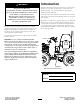
Introduction WARNING CALIFORNIA Proposition 65 Warning This product contains a chemical or chemicals known to the State of California to cause cancer, birth defects, or reproductive harm. Diesel engine exhaust and some of its constituents are known to the State of California to cause cancer, birth defects, and other reproductive harm. Read this information carefully to learn how to operate and maintain your product properly and to avoid injury and product damage.
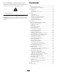
Contents This manual identifies potential hazards and has safety messages identified by the safety alert symbol (Figure 2), which signals a hazard that may cause serious injury or death if you do not follow the recommended precautions. Safety ........................................................................... 4 Safe Operating Practices........................................... 4 Safety and Instructional Decals ................................. 7 Product Overview ..................................
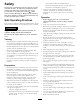
Safety Improper use or maintenance by the operator or owner can result in injury. To reduce the potential for injury, comply with these safety instructions and always pay attention to the safety alert symbol , which means: Caution, Warning, or Danger—personal safety instruction. Failure to comply with the instruction may result in personal injury or death. • Operation • Before digging, have the area marked for Safe Operating Practices This product is capable of amputating hands and feet.
• Do not operate near drop-offs, ditches, or embankments. • Ensure that the area is clear of other people before • • • • • • • • • • The machine could suddenly turn over if a wheel goes over the edge of a cliff or ditch, or if an edge caves in. operating the machine. Stop the machine if anyone enters the area. Never leave a running machine unattended. Always stop the engine, set the parking brake, and remove the key before leaving. Never jerk the controls; use a steady motion.
• Charge batteries in an open well ventilated area, away from spark and flames. Unplug the charger before connecting or disconnecting it from the battery. Wear protective clothing and use insulated tools. • Keep all parts in good working condition and all hardware tightened. Replace all worn or damaged decals. • Keep nuts and bolts tight. Keep equipment in good condition. • Never tamper with safety devices. • Keep the machine free of grass, leaves, or other debris build-up. Clean up oil or fuel spillage.
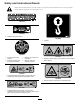
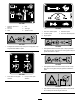
Safety and Instructional Decals Safety decals and instructions are easily visible to the operator and are located near any area of potential danger. Replace any decal that is damaged or lost. 117-2718 114-9600 1. Read the Operator's Manual. 125–4967 1. Lift point 117-3276 1. Engine coolant under pressure 3. Warning—do not touch the hot surface. 2. Explosion hazard—read the Operator's Manual. 4. Warning—read the Operator's Manual. 125-6671 1.
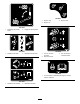
125–6677 1. Engine—stop 3. Engine—start 2. Engine—run 125–6674 1. Disengage the parking brake. 2. Engage the parking brake. 125–6675 1. Raise/lower the plow. 125–6678 2. Raise/lower the trencher. 1. Turn the trencher clockwise. 2. Stop the trencher. 3. Turn the trencher counterclockwise. 125–6679 1. For information on preheating the engine, read the Operator’s Manual. 125–6676 1. Raise/lower the trencher. 2. Raise/lower the plow.
125–6680 1. Read the Operator’s Manual. 2. Turn left 4. Fast 3. Slow 6. Traction control 125-6683 5. Turn right 1. Pull out for fastest speed 4. Decrease speed 2. Increase speed 5. Push in for slowest speed 3. Engine speed 125–6681 125–6684 1. Entanglement hazard—keep away from moving parts; keep all guards and safeties in place. 1. Cutting/dismemberment hazard, plow—keep bystanders away from the plow; stay away from moving parts; keep all guards and safeties in place. 125–6686 1.
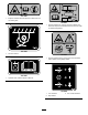
125–6688 1. Explosion hazard—Read the Operator’s Manual; Do not use starting fluid. 125–8487 1. Crushing hazard, tire—read the Operator’s Manual; the extension step must be attached when the tires are in wide or doubled configuration. 125–6694 1. Tie down location 125–8491 1. Crushing hazard, warning—keep away from articulated joints; replace missing safety shields. 125–8483 1. Hydraulic fluid; read the Operator’s Manual. 125–8488 1. Turn clockwise 2. Stop rotation 10 3.
106-9290 1. Inputs 5. In seat 2. Not active 6. Power Take-off (PTO) 9. Outputs 13. Start 10. Power Take Off (PTO) 3. High temperature shutdown 7. Parking brake Off 11. Start 4. High temperature warning 12. Energize to Run (ETR) 8. Neutral 14. Power 125–6673 1. Warning—read the Operator’s Manual. 4. Warning—keep bystanders away from the machine. 7. Explosion hazard; shock hazard—call the local utilities before digging underground. 2.
Product Overview 1 2 3 4 5 6 8 7 g019007 9 Figure 3 1. Control panel 4. Engine-oil filter 7. Front tie-down bar 2. Hood latch 5. Engine-oil dipstick 8. Air cleaner 3. Hood handle 6. Fuel filter 9. Rear tie-down bar Controls You can rotate the knob to make small adjustments to the engine speed. Rotate the knob counterclockwise to increase engine speed and clockwise to decrease engine speed. Become familiar with all the controls (Figure 4) before you start the engine and operate the machine.
Move the lever to the neutral position to stop the machine. Key Switch From the neutral position, push the lever slightly for forward ground travel. Push the lever farther to increase the forward ground speed. Pull the lever slightly to decrease the forward ground speed. The key switch, used to start and stop the engine, has 3 positions: on, off, and start. To start the engine, rotate the key to the start position. Release the key when engine starts and it will move automatically to the on position.
Neutral Indicator Light Operation This light illuminates when all control levers are in the neutral position. Note: Determine the left and right sides of the machine from the normal operating position. Specifications Important: Before operating, check the fuel and oil level, and remove debris from the machine. Also, ensure that the area is clear of people and debris. You should also know and have marked the locations of all utility lines.
Filling the Fuel Tank 1. Lift the operator seat to access the fuel tank. 2. Remove the fuel tank cap (Figure 7). DANGER 1 In certain conditions, fuel is extremely flammable and highly explosive. A fire or explosion from fuel can burn you and others and can damage property. • Fill the fuel tank outdoors, in an open area, when the engine is cold. Wipe up any fuel that spills. • Never fill the fuel tank inside an enclosed trailer.
Note: If the outdoor temperature is below freezing, store the machine in a garage to keep it warmer and aid in starting. trencher-digging-control, or creep-control levers are moved from the Neutral position. 5. Release the parking brake. Note: Do not start the plow vibration until the blade tip has entered the ground. Stopping the Engine 1. Move the throttle lever to the Slow position. 6. Pull the PTO switch to start the cable plow vibration. 2. Lower any attachments to the ground. 7.
4. Install the new skid shoes and secure them with the previously removed hardware (Figure 10). Rotating the Wheels You can install the wheels to provide a narrow or a wide overall width of machine. Install the wheels with the deep concave toward the machine for operation in tight areas or the shallow concave toward the machine for wider stability. Important: Only operate on level ground with the narrow wheel configuration. Tire Size G025774 Ply Rating Figure 9 2. Pin 1. Snap-ring pin 3.
Note: Use the rear tie-down loop (Figure 14) to secure the machine. g023499 Figure 12 1 g018922 Figure 14 Transporting the Machine 1. Rear tie-down loop Loading the Machine 10. Measure the distance from the ground to the highest point of the machine to determine the clearance height. Important: Ensure that the trailer and ramp can support both your weight plus the weight of the machine with any attachments. 11. Remove the blocks from the front and rear of the trailer wheels. 2.
Maintenance Note: Determine the left and right sides of the machine from the normal operating position. Recommended Maintenance Schedule(s) Maintenance Service Interval Maintenance Procedure After the first 25 hours • Replace the hydraulic filter. After the first 50 hours • Change the engine oil and filter. After the first 250 hours • Change the hydraulic fluid. Before each use or daily • Grease the machine (Grease immediately after every washing).
Important: Refer to your Engine Operator's Manual for additional procedures. Note: Looking for an Electrical Schematic or Hydraulic Schematic for your machine? Download a free copy of the schematic by visiting www.Toro.com and searching for your machine from the Manuals link on the home page. CAUTION If you leave the key in the ignition switch, someone could accidently start the engine and seriously injure you or other bystanders. Remove the key from the ignition before you do any maintenance.
Engine Maintenance Servicing the Air Cleaner Service Interval: Before each use or daily—Check the air filter service indicator light (more frequently if conditions are dusty or sandy). Every 25 hours—Remove the air cleaner cover, clean out any debris, and check the air filter service indicator light (more frequently if conditions are dusty or sandy). Every 1,000 hours/Yearly (whichever comes first)—Replace the safety air filter (more frequently if conditions are dusty or sandy).
Replacing the Filters 4. Clean around the oil dipstick (Figure 22). 1. Gently slide the primary filter out of the air cleaner body (Figure 20). Avoid knocking the filter into the side of the body. 1 2. Inspect the new filter(s) for damage by looking into the filter while shining a bright light on the outside of the filter. Holes in the filter will appear as bright spots. Inspect the element for tears, an oily film, or damage to the rubber seal. If the filter is damaged, do not use it. 3.
Changing the Oil Filter CAUTION 1. Drain the oil from the engine; refer to Changing the Oil (page 22). Components will be hot if the machine has been running. If you touch hot components you may be burned. 2. Place a shallow pan or rag under the filter to catch the oil. Allow the machine to cool before performing maintenance or touching components under the hood. 3. Remove the old filter (Figure 25) and wipe the surface of the gasket seal on the filter head. 1 4.
Fuel System Maintenance 1. Ensure that the fuel tank is at least half full. 2. Open the hood. 3. Open the air bleed screw on the fuel injection pump (Figure 26). DANGER Under certain conditions, diesel fuel and fuel vapors are highly flammable and explosive. A fire or explosion from fuel can burn you and others and can cause property damage. • Use a funnel and fill the fuel tank outdoors, in an open area, when the engine is off and is cold. Wipe up any fuel that spills.
Draining the Fuel Filter/Water Separator Electrical System Maintenance Service Interval: Every 50 hours—Drain water and other contaminants from the fuel filter/water separator. Servicing the Battery 1. Locate the fuel filter on the right side of the engine (Figure 27) and place a clean container under it. Service Interval: Every 100 hours—Check the battery electrolyte level (replacement battery only). Every 250 hours—Check the battery cable connections.
Important: Do not overfill the battery because electrolyte (sulfuric acid) can cause severe corrosion and damage to the chassis. 3. Slide the battery tray out of the frame. 4. Look at the side of the battery. Note: The electrolyte must be up to the Upper line (Figure 29). Do not allow the electrolyte to fall below the Lower line (Figure 29). 5. Wait 5 to 10 minutes after filling the battery cells.
Servicing the Transmission and Axles Drive System Maintenance Transmission oil specification: SAE 80W140 API classification level GL5 Checking the Tire Pressure Transmission oil capacity: approximately 0.47 L (0.5 qt) Service Interval: Before each use or daily Toro Premium Gear Oil is available from an Authorized Service Dealer. See the parts catalog for part numbers. Maintain the air pressure in the tires as specified. Check the tires when they are cold to get the most accurate reading.
Changing the Transmission Oil Note: The oil level should be even with the bottom of the fill plug hole. Service Interval: Every 1,000 hours/Yearly (whichever comes first) 4. Add oil to raise the oil level up to the bottom of the fill plug hole. 1. Park the machine on a level surface, lower any attachments, and stop the engine. 5. Install the fill plug. 2. Clean the area around the fill plug with a cleaning solvent (Figure 33). 6. Repeat for the other differential. Changing the Axle Oil 1 1.
Cooling System Maintenance Checking and Adding the Engine Coolant Servicing the Cooling System Clean any debris off of the screen, oil cooler, and front of the radiator daily and more frequently when operating conditions are extremely dusty or sandy. Service Interval: Before each use or daily Service Interval: Before each use or daily—Clean the radiator. The cooling system is filled with a 50/50 solution of water and permanent ethylene glycol antifreeze.
Belt Maintenance Controls System Maintenance Checking the Alternator Drive Belt Tension The factory adjusts the controls before shipping the machine However, after many hours of use, you may need to adjust the controls. Service Interval: Every 1,000 hours Important: To adjust the controls properly, complete each procedure in the order listed. 1. Push the drive belt with your thumb in the area shown to check the tension (Figure 37). Note: The deflection should be between 7 to 9 mm (0.28 to 0.
Hydraulic System Maintenance 4. Tighten the set-screw catch until the catch bottoms out against the steering control pivot, then loosen the screw 1/2 to 3/4 turn. 5. Install the access panel. Servicing the Hydraulic System Adjusting the Traction Drive for Neutral Hydraulic fluid reservoir capacity: 25.8 L (6.8 US gallons) When positioned on a level surface, the machine must not creep when the traction pedal is released.
1 1 g018923 Figure 40 g018957 Figure 41 1. Hydraulic-oil filter 1. Hydraulic tank 5. Apply a thin coat hydraulic fluid to the rubber gasket on the replacement filter. 5. Remove the cap from the filler neck and check the fluid level on the dipstick (Figure 42). 6. Install the replacement hydraulic filter onto the filter head. Tighten it clockwise until the filter contacts the filter head, then tighten the filter an additional 3/4 turn. The fluid level should be between the marks on the dipstick.
12. Install the hose shown in Figure 43. 5. Pinch the hose shown in Figure 43 and remove the clamp on the other end attached to the tee adapter. 13. Fill the hydraulic tank with approximately 25.8 L (6.8 US gallons) of Toro premium all season hydraulic fluid ISO VG 46; refer to Checking the Hydraulic Fluid Level (page 32). Dispose of the used oil at a certified recycling center. 14. Install the dipstick cap. 15. Start the engine and let it run for a few minutes. 16. Stop the engine. 17.
ROPS Maintenance 3. Inspect the ROPS for cracks, rust, or holes in the ROPS and component parts. Note: Age, weather, and accidents cause damage to the ROPS and ROPS parts. If you have any doubts about the ROPS system, contact an Authorized Service Dealer. Checking and Servicing the ROPS Checking and Caring for the Seat Belt Replacing a Damaged ROPS System Before you operate the machine, always ensure that the ROPS and the seat belt are properly installed and in good working order.
Cleaning Storage 1. Lower any attachments, stop the engine, and remove the key. Removing Debris from the Machine 2. Remove dirt and grime from the entire machine. Important: You can wash the machine with mild detergent and water. Do not pressure wash the machine. Avoid excessive use of water, especially near the control panel, engine, hydraulic pumps, and motors.
Troubleshooting Problem The starter does not crank. Possible Cause 1. The controls are not in the neutral position. 1. Move all of the controls to the Neutral position. 2. The electrical connections are corroded or loose. 3. A fuse is blown or loose. 4. The battery is discharged. 5. The relay or switch is damaged. 2. Check the electrical connections for good contact. 3. Correct or replace the fuse. 4. Charge the battery or replace it. 5. Contact your Authorized Service Dealer. 6.
Problem The engine starts, but does not keep running. Possible Cause 1. The fuel tank vent is restricted. 1. Loosen the cap. If the engine runs with the cap loosened, replace the cap. 2. There is dirt or water is in the fuel system. 3. The fuel filter is clogged. 4. There is air in the fuel system. 2. Drain and flush the fuel system; add fresh fuel. 3. Replace the fuel filter. 4. Bleed the nozzles and check for air leaks at fuel hose connections and fittings between the fuel tank and engine. 5.
Problem The engine overheats. Possible Cause 1. More coolant is needed. 1. Check and add coolant. 2. There is restricted air flow to the radiator. 3. The crankcase oil level is incorrect. 4. The engine load is too excessive. 2. Inspect and clean the side panel screens with every use. 3. Fill or drain the oil to the full mark. 4. Reduce the load; use lower ground speed. 5. Drain and flush the fuel system; add fresh fuel. 6. Contact your Authorized Service Dealer. 7.
Problem The engine loses power. Possible Cause 1. The engine load is excessive. 1. Reduce the load; use lower ground speed. 2. The crankcase oil level is incorrect. 3. The air cleaner filters are dirty. 4. There is dirt, water, stale fuel, or incorrect fuel is in the fuel system. 5. The engine is overheating. 2. Fill or drain to the full mark. 3. Service the air filters. 4. Drain and flush the fuel system; add fresh fuel. 5. Refer to troubleshooting item The engine is overheating. 6.
Toro Compact Utility Equipment Warranty Compact Utility Equipment (CUE) Products A One-Year Limited Warranty Conditions and Products Covered Items and Conditions Not Covered The Toro Company and its affiliate, Toro Warranty Company, pursuant to an agreement between them, jointly warrant your Toro Compact Utility Equipment (“Product”) to be free from defects in materials or workmanship.