
Operator's Manual

G025774
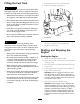
Figure9
1.Snap-ringpin
2.Pin
3.Pullthe2pinsoutoftheblade.
Note:Theplowbladesareheavy.Makesurethat1
personisholdingthebladewhiletheotherpersonis
removingthepins.
4.Placethenewbladeintotheplowbladeassemblyand
secureitwith2pinsand2snap-ringpins.
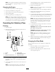
RemovingandInstallingtheSkidShoes
1.Raisetheplowabout91.4cm(36inches)offthe
ground.
2.Stoptheengineandremovethekey.
3.Removethe4bolts,4nuts,and8washersfromthe
skidshoes(Figure10).
1
2
3
4
g021986
5
Figure10
1.Nut4.Washer
2.Washer5.Bolt
3.Skidshoes
4.Installthenewskidshoesandsecurethemwiththe
previouslyremovedhardware(Figure10).
RotatingtheWheels
Youcaninstallthewheelstoprovideanarroworawide
overallwidthofmachine.Installthewheelswiththedeep
concavetowardthemachineforoperationintightareasor
theshallowconcavetowardthemachineforwiderstability.
Important:Onlyoperateonlevelgroundwiththe
narrowwheelconguration.
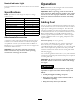
Pressure
TireSize
PlyRating
kPapsi
23x10.5x12413820
26x12x12820730
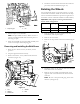
1.Parkthemachineonalevelsurface,lowerany
attachments,andstoptheengine.
2.Removetherearwheels.
3.Removethestepextensionfromthemachine(Figure
11).
g022223
Figure11
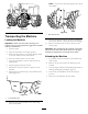
4.Installthewheelsontheoppositesideofthemachine
fromwhicheachwasremoved.
5.Removethefrontwheelsandinstallthemonthe
oppositesideofthemachinefromwhicheachwas
removed.
Note:Besuretokeepthetreadgoinginthesame
direction(seeFigure12).
17