Form No. 3374-144 Rev C P40 Vibratory Plow Pro Sneak 360 Vibratory Plow Model No. 25402—Serial No. 313000001 and Up Model No. 25402E—Serial No. 313000001 and Up Register at www.Toro.com.
This manual identifies potential hazards and has safety messages identified by the safety alert symbol (Figure 2), which signals a hazard that may cause serious injury or death if you do not follow the recommended precautions. Introduction The vibratory plow is an attachment designed for use on the Toro Pro Sneak machine to pull flexible pipe and cable into and through soil.
Safety WARNING When the plow is out of the ground, bystanders could be injured by the swinging plow, and/or the machine could be overturned by the inertia of the swinging plow, crushing you or bystanders. Improper use or maintenance by the operator or owner can result in injury. To reduce the potential for injury, comply with these safety instructions and those in the machine Operator's Manual.
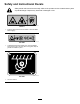
Safety and Instructional Decals Safety decals and instructions are easily visible to the operator and are located near any area of potential danger. Replace any decal that is damaged or lost. decal125-6671 125-6671 1. Explosion hazard; electric shock hazard—call local utilities before digging. decal125-6684 125–6684 1. Cutting/dismemberment hazard, plow—keep bystanders away from the plow; stay away from moving parts; keep all guards and safeties in place. decal125-6694 125–6694 1.
Setup Loose Parts Use the chart below to verify that all parts have been shipped. Procedure Description Use Qty. 1 Locknuts Bolts Swing lock Washers Lynch pin Pivot pin Lift pin Snap ring Clevis pin 4 4 1 10 2 2 1 4 1 Attach the plow. 2 No parts required – Route the hoses.
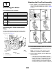
Attaching the Plow Pivot Assembly 1 1. Attaching the Plow Place 1 washer (1 inch) between the first and second plates and between the fourth and fifth plates on the plow assembly as shown in Figure 4; Box A.
sixth plates on the plow assembly (Figure 4; Box B). • If the 26 inch tires are installed, place the pivot assembly onto the attachment plate so that the top ledge on the attachment plate is between the first and second plates on the plow assembly and the bottom ledge of the attachment plate is between the fourth and fifth plates on the plow assembly (Figure 4; Box C). 4.
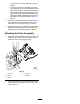
2 Routing the Hoses No Parts Required Connect the hose from port A to port A and repeat for port B to port B (Figure 6). g022390 Figure 8 g022389 Figure 6 1. Port A 2. Port B 3. Port A 4. Port B Connect the existing hoses as shown in Figure 7 and Figure 8.
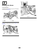
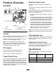
Direction Control Lever Product Overview This lever controls the direction and speed of the machine. Controls This lever has 5 positions: forward, reverse, neutral, right, and left. The machine will move in the direction that you move the lever. The farther you push or pull the lever, the faster the machine will move. • Move the lever to the neutral position to stop the machine. • From the neutral position, push the lever slightly for forward ground travel.
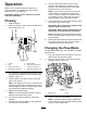
Operation 8. Refer to your machine Operator’s Manual for more information on installing and removing the attachments on your machine. Note: The more you push the lever from the neutral position, the faster the machine will travel. The lever will stay in this position when you release the lever. Move the lever to the Neutral position to stop the machine travel. Important: Always use the machine to lift and move the attachment. Plowing 1. 2.
4. Place the new blade into the plow blade assembly and secure it with 2 pins and 2 snap-ring pins. Removing and Installing the Skid Shoes 1. Raise the plow about 91.4 cm (36 inches) off the ground. 2. Stop the engine and remove the key. 3. Remove the 4 bolts, 4 nuts, and 8 washers from the skid shoes (Figure 12). g021986 Figure 12 1. Nut 2. Washer 3. Skid shoes 4. 4. Washer 5. Bolt Install the new skid shoes and secure them with the previously removed hardware (Figure 12).
Maintenance Recommended Maintenance Schedule(s) Maintenance Service Interval Maintenance Procedure Before each use or daily • Grease the plow. Before storage • Grease the plow. CAUTION If you leave the key in the ignition switch, someone could start the engine. Accidental starting of the engine could seriously injure you or other bystanders. Remove the key from the ignition switch before you do any maintenance.
Storage 1. Stop the engine and remove the key. 2. Remove dirt and grime from the external parts of the attachment with a mild detergent and water. Important: Do not pressure wash the attachment. High-pressure washing can damage the electrical system and hydraulic valves or deplete grease. 3. Grease the attachment; refer to Greasing the Plow (page 12). 4. Check and tighten all bolts, nuts, and screws. Repair or replace any part that is damaged. 5.
Troubleshooting Problem The plow does not operate. Possible Cause Corrective Action 1. There is an obstruction in a hydraulic hose. 1. Find and remove the obstruction. 2. A hydraulic hose is kinked. 3. The auxiliary valve on the machine is not opening. 2. Replace the kinked hose 3. Repair the valve.
Notes: