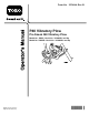
Form No. 3374-144 Rev B P40 Vibratory Plow Pro Sneak 360 Vibratory Plow Model No. 25402—Serial No. 313000001 and Up Model No. 25402E—Serial No. 313000001 and Up g019060 Register at www.Toro.com.
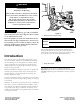
WARNING 1 CALIFORNIA Proposition 65 Warning This product contains a chemical or chemicals known to the State of California to cause cancer, birth defects, or reproductive harm. The engine exhaust from this product contains chemicals known to the State of California to cause cancer, birth defects, or other reproductive harm. DANGER g019062 There may be buried power, gas, and/or telephone lines in the work area. If you dig into them, a shock or an explosion may occur. Figure 1 1.
Contents Safety Introduction .................................................................. 2 Safety ........................................................................... 3 Safety and Instructional Decals ................................. 4 Setup ............................................................................ 5 1 Attaching the Plow................................................ 5 2 Routing the Hoses................................................. 6 Product Overview ...............
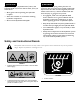
CAUTION WARNING Hydraulic couplers, hydraulic lines/valves, and hydraulic fluid may be hot and can burn you if you touch them. Hydraulic fluid escaping under pressure can penetrate skin and cause injury. Fluid accidentally injected into the skin must be surgically removed within a few hours by a doctor familiar with this form of injury or gangrene may result. • Wear gloves when operating the hydraulic couplers.
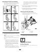
Setup Loose Parts Use the chart below to verify that all parts have been shipped. Procedure Description Use Qty. 1 Locknuts Bolts Swing lock Washers Lynch pin Pivot pin Lift pin Snap ring Clevis pin 4 4 1 10 2 2 1 4 1 Attach the plow. 2 No parts required – Route the hoses. 1 Attaching the Plow Attachment Plate Attaching the Plow Secure the attachment plate to the machine using 4 bolts and 4 locknuts and torque to 321-392 N-m (237-289 ft-lb) (Figure 3).
Attaching the Plow Pivot Assembly and second plates on the plow assembly and the bottom ledge of the attachment plate is between the fourth and fifth plates on the plow assembly (Figure 4; Box C). 1. Place 1 washer (1 inch) between the first and second plates and between the fourth and fifth plates on the plow assembly as shown in Figure 4; Box A. 4. Place the 2 plow pivot pins through the hole on the plates on the plow assembly, and secure them using the 2 lock pins (Figure 4; Box D). A 5.
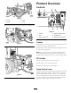
Product Overview 2 3 1 Controls 1 2 3 4 g022389 4 Figure 6 1. Port A 2. Port B 3. Port A 4. Port B Connect the existing hoses as shown in Figure 7 and Figure 8. g018966 5 6 Figure 9 1. Throttle 2. PTO 4. Directional control lever 5. Parking brake 3. Creep control lever 6. Attachment control lever Throttle g022388 Figure 7 Push the button at the center of the knob, and pull the knob to increase the engine speed (Figure 9).
Direction Control Lever Operation This lever controls the direction and speed of the machine. Refer to your machine Operator’s Manual for more information on installing and removing the attachments on your machine. This lever has 5 positions: forward, reverse, neutral, right, and left. Important: Always use the machine to lift and move the attachment. The machine will move in the direction that you move the lever. The farther you push or pull the lever, the faster the machine will move.
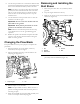
Removing and Installing the Skid Shoes 8. Use the creep control lever to control the direction and speed of the machine during plowing. The machine will move in the same direction that you move the lever. 1. Raise the plow about 91.4 cm (36 inches) off the ground. Note: The more you push the lever from the neutral position, the faster the machine will travel. The lever will stay in this position when you release the lever. Move the lever to the Neutral position to stop the machine travel. 2.
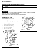
Maintenance Recommended Maintenance Schedule(s) Maintenance Service Interval Maintenance Procedure Before each use or daily • Grease the plow. Before storage • Grease the plow. CAUTION If you leave the key in the ignition switch, someone could start the engine. Accidental starting of the engine could seriously injure you or other bystanders. Remove the key from the ignition switch before you do any maintenance.
Storage 1. Stop the engine and remove the key. 2. Remove dirt and grime from the external parts of the attachment with a mild detergent and water. Important: Do not pressure wash the attachment. High-pressure washing can damage the electrical system and hydraulic valves or deplete grease. 3. Grease the attachment; refer to Greasing the Plow (page 10). 4. Check and tighten all bolts, nuts, and screws. Repair or replace any part that is damaged. 5.
Troubleshooting Problem The plow does not operate. Possible Cause Corrective Action 1. There is an obstruction in a hydraulic hose. 1. Find and remove the obstruction. 2. A hydraulic hose is kinked. 3. The auxiliary valve on the machine is not opening. 2. Replace the kinked hose 3. Repair the valve.
Notes: 13
Notes: 14
Notes: 15
Toro Compact Utility Equipment Warranty Compact Utility Equipment (CUE) Products A One-Year Limited Warranty Conditions and Products Covered The Toro Company and its affiliate, Toro Warranty Company, pursuant to an agreement between them, jointly warrant your Toro Compact Utility Equipment (“Product”) to be free from defects in materials or workmanship.