Form No. 3406-344 Rev A Pro Sneak 365 Vibratory Plow Model No. 25403—Serial No. 316000001 and Up Register at www.Toro.com.
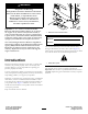
WARNING CALIFORNIA Proposition 65 Warning This product contains a chemical or chemicals known to the State of California to cause cancer, birth defects, or reproductive harm. Diesel engine exhaust and some of its constituents are known to the State of California to cause cancer, birth defects, and other reproductive harm.
Contents Troubleshooting ...........................................................40 Safety ........................................................................... 4 Safe Operating Practices........................................... 4 Safety and Instructional Decals ................................. 7 Product Overview .........................................................13 Controls ...............................................................13 Specifications .................................
Safety This machine has been designed in accordance with ANSI B71.4 • Improper use or maintenance by the operator or owner can result in injury. To reduce the potential for injury, comply with these safety instructions and always pay attention to the safety alert symbol , which means: Caution, Warning, or Danger—personal safety instruction. Failure to comply with the instruction may result in personal injury or death. Safe Operating Practices This product is capable of amputating hands and feet.
• Allow adequate space when turning this unit. • Slow down, watch for traffic, and use caution when • • • • • • • • operating near or crossing roadways and sidewalks. Use care when approaching blind corners, shrubs, trees, or other objects that may obscure vision. Ensure that you operate the machine in areas where there are no obstacles in close proximity to the operator.
• Disengage the auxiliary hydraulics, lower the attachment, • Battery acid is poisonous and can cause burns. Avoid set the parking brake, shut off the engine, and remove the key. Wait for all movement to stop before adjusting, cleaning, or repairing. contact with skin, eyes, and clothing. Protect your face, eyes, and clothing when working with a battery. • Battery gases can explode. Keep cigarettes, sparks and • Carefully release pressure from components with stored flames away from the battery.
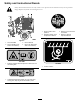
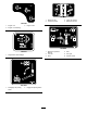
Safety and Instructional Decals Safety decals and instructions are easily visible to the operator and are located near any area of potential danger. Replace any decal that is damaged or lost. 106-6755 1. Engine coolant under pressure 3. Warning—do not touch the hot surface. 2. Explosion hazard—read the Operator's Manual. 4. Warning—read the Operator's Manual. Figure 4 1. Decal 125-6688 2. Decal 120-0627 (both sides of the machine) 3. Decal 106-6755 4.
125–8483 1. Hydraulic fluid; read the Operator’s Manual. Figure 5 1. Decal 125-4963 2. Decal 130-4291 125–6672 3. Decal 125-8483 4. Decal 125-6672 1. Crushing hazard—stay away from articulated joints. 125–4963 1. Warning—keep hands away from hot surfaces 130-4291 Figure 6 1. Regeneration inhibit—read the Operator's Manual. 1. Decal 130-7360 2. Decal 130-4341 3. Decal 125-6674 8 4. Decal 130-7361 5.
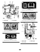
130-7361 130-7360 1. Raise the plow 3. Lower the trencher 2. Lower the plower 4. Raise the trencher 3. Engine—start 1. Engine—off ACK 130-4341 2. Engine—run/warming 125–6680 130-4341 1. Regeneration acknowledge 125–6674 1. Disengage the parking brake. 2. Engage the parking brake. 9 1. Read the Operator’s Manual. 2. Turn left 4. Fast 3. Slow 6. Traction control 5.
130-4343 Figure 7 1. Decal 117-2718 2. Decal 130-4343 3. Decal 130–4340 4. Decal 127–1824 1. Warning—read the Operator's Manual. 5. Warning—keep bystanders away. 2. Warning—do not operate the machine unless you have received instruction. 6. Warning—keep away from moving parts; keep all guards and shields in place. 3. Warning—wear a seatbelt. 7. Warning—do not operate the trencher while using the plow; do not operate the plow while using the trencher. 4. Warning—wear hearing 8.
125–8487 1. Crushing hazard, tire—read the Operator’s Manual; the extension step must be attached when the tires are in wide or doubled configuration. 127-1824 2. For more information on 1.
7-1822 Figure 9 1. Decal 127-1822 2. Decal 125-4967 3. Decal 125-6671 4. Decal 125-6684 5. Decal 125-6694 1. The engine cannot start with the plow active. 4. No vibration 2. High vibration 5. The engine can start with the plow inactive. 3. Low vibration 125-6671 1. Explosion hazard; electric shock hazard—call local utilities before digging. 125–4967 1. Lift point 125–6684 1.
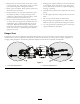
Controls Product Overview 3 4 Become familiar with all of the controls before you start the engine and operate the machine. 5 6 Throttle 2 The throttle controls the engine speed. Push the knob to increase the engine speed. Pull the knob to decrease the engine speed. 1 Parking-Brake Lever To set the parking brake, pull the lever up and push it forward. To release the parking brake, pull the lever back and down. g025662 Attachment Control Lever Figure 10 Right-side view 1. Vibratory plow 3.
Creep-Control Lever The creep-control lever controls the direction and speed of the machine while the attachments are in use. To go forward, push the lever forward. To reverse, pull the lever backward. The further you push or pull the lever, the faster the machine travels. The creep-control lever will not return to the NEUTRAL position on its own. Hour Meter The hour meter displays the number of hours of operation that have been logged on the machine.
Regeneration-Request Light Regeneration-Acknowledge Switch This light illuminates along with the high-temperature-exhaust indicator when a regeneration is in process. If this light is illuminated on its own, a stationary regeneration is possible. When a regeneration is requested but the regeneration inhibit switch is active, this light blinks. If this light is illuminated along with the check engine light, the DPF needs servicing; contact your Authorized Service Dealer for more information.
Adding Fuel Operation Use ultra low sulfur diesel fuel (ULSD) in the engine of this machine. The use of other fuels can cause the loss of engine power and high fuel consumption. The diesel fuel used in this machine must meet the specifications of D975 of ASTM International. See your diesel fuel distributor. The D975 standard defines 2 ULSD standards, Grade No. 2-D S15 (regular ULSD) and Grade No. 1-D S15 (a higher volatility ULSD fuel with a lower gelling temperature than regular ULSD).
Filling the Fuel Tank 1. Park the machine on a level surface, lower any attachments, shut off the engine, and remove the key. DANGER 2. Lift the operator seat to access the fuel tank. 3. Remove the fuel tank cap (Figure 15). In certain conditions, fuel is extremely flammable and highly explosive. A fire or explosion from fuel can burn you and others and can damage property. • Fill the fuel tank outdoors, in an open area, when the engine is cold. Wipe up any fuel that spills.
Note: If the outdoor temperature is below freezing, store the machine in a garage to keep it warmer and aid in starting. 5. Release the parking brake. Note: Do not start the plow vibration until the blade tip has entered the ground. 6. Move the vibratory-plow lever to start the plow vibration. Shutting Off the Engine 1. Move the throttle lever to the SLOW position. 7. Slowly lower the plow blade into the ground as the machine moves forward. 2. Lower any attachments to the ground. 3.
Rotating the Wheels You can install the wheels to provide a narrow or a wide overall width of machine. Install the wheels with the deep concave toward the machine for operation in tight areas or the shallow concave toward the machine for wider stability. Important: Only operate on level ground with the narrow wheel configuration. G025774 Figure 17 Ply Rating 23 x 10.5 x 12 26 x 12 x 12 Pressure kPa psi 4 138 20 8 207 30 1.
Transporting the Machine Loading the Machine Important: Ensure that the trailer and ramp can support both your weight plus the weight of the machine with any attachments. 1. Start the engine. 2. Move the attachments to transport position. 3. Secure the trailer hitch to your vehicle and put a block at the front and rear of the trailer wheels. 4. Move the machine slowly onto the trailer. g023499 Figure 20 5. Lower the attachments onto the trailer and set the parking brake. 6.
1 g018922 Figure 22 1. Rear tie-down loop 10. Measure the distance from the ground to the highest point of the machine to determine the clearance height. 11. Remove the blocks from the front and rear of the trailer wheels. Important: After transporting the machine a few miles, stop the truck, ensure that the tie-downs are still tight and that the machine has not moved on the trailer. Unloading the Machine 1. Put a block at the front and rear of the machine and trailer wheels. 2.
Maintenance Note: Determine the left and right sides of the machine from the normal operating position. Important: Refer to your engine Operator's Manual for additional maintenance procedures. Note: Download a free copy of the Electrical Schematic or Hydraulic Schematic for your machine by visiting www.Toro.com and searching for your machine from the Manuals link on the home page.
Maintenance Service Interval Maintenance Procedure Every 1,000 hours • • • • • Change the transmission oil. Change the engine coolant (See an Authorized Service Dealer). Check the alternator drive belt tension. Replace the hydraulic filter. Change the hydraulic fluid. Every 1,500 hours • Replace all moving hydraulic hoses. Every 2,000 hours • Replace the fuel lines and connections. Every 3,000 hours • Clean or replace the diesel particulate filter.
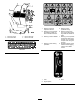
Engine Maintenance Servicing the Air Cleaner Service Interval: Before each use or daily—Check the air filter service indicator light (more frequently if conditions are dusty or sandy). Every 250 hours—Remove the air cleaner cover, clean out any debris, and check the air filter service indicator light (more frequently if conditions are dusty or sandy). Every 500 hours—Replace the air filter (more frequently if conditions are dusty or sandy).
Replacing the Filters SAE 20W -50 If the air filter light illuminates, perform the following steps. SAE 15W -40 1. Gently slide the primary filter out of the air cleaner body (Figure 27). SAE 10W -30 Note: Avoid knocking the filter into the side of the body. SAE 5W -30 SAE 0W -30 2. Inspect the new filter(s) for damage by looking into the filter while shining a bright light on the outside of the filter.
Changing the Oil Filter Note: When using different oil, drain all old oil from the crankcase before adding new oil. 1. Drain the oil from the engine; refer to Changing the Engine Oil (page 26). 5. Install the oil fill cap and dipstick. 6. Close the engine cover and secure it with the latches. 2. Place a shallow pan or rag under the filter to catch the oil. Changing the Engine Oil 3. Remove the old filter (Figure 31) and wipe the surface of the gasket seal on the filter head. 1.
Servicing the Diesel Particulate Filter (DPF) Fuel System Maintenance Service Interval: Every 3,000 hours DANGER Over time, ash accumulates in the DPF and a background regeneration is not sufficient to unclog the filter. When this occurs, the regeneration request and check engine lights illuminate on the control panel. At this time, the filter requires a stationary regeneration or needs to be replaced; contact your Authorized Service Dealer for more information.
Replacing the Fuel Filter Canister Electrical System Maintenance Service Interval: Every 500 hours—Replace the fuel filter/water separator. Servicing the Battery 1. Clean the filter head and the outside of the fuel filter. Service Interval: Every 100 hours—Check the battery electrolyte level (replacement battery only). 2. Turn the filter counterclockwise and remove the filter from the filter head. 3. Lubricate the gasket on the new filter canister with clean oil.
Drive System Maintenance Servicing the Tires Checking the Tires and Lug Nuts Service Interval: Before each use or daily—Check the tire pressure. Before each use or daily—Check the lug nuts. G025670 Figure 32 1. Positive battery post 3. Red (+) charger lead 2. Negative battery post 4. Black (-) charger lead • Do not exceed the rated tire pressure. To ensure long tire life and safe handling, check tire pressure daily, refer to Checking the Tire Pressure (page 29).
Changing the Transmission Oil Servicing the Transmission and Axles Service Interval: Every 1,000 hours/Yearly (whichever comes first) Transmission oil specification: SAE 80W140 API classification level GL5 1. Park the machine on a level surface, lower any attachments, and shut off the engine. Transmission oil capacity: approximately 0.47 L (0.5 US qt) 2. Clean the area around the fill plug with a cleaning solvent (Figure 35).
Cooling System Maintenance Note: The oil level should be even with the bottom of the fill plug hole. 4. Add oil to raise the oil level up to the bottom of the fill plug hole. Servicing the Cooling System 5. Install the fill plug. 6. Repeat for the other differential. Service Interval: Before each use or daily—Check and refill the engine coolant. Changing the Axle Oil Every 100 hours—Check the cooling system hoses. 1. Place a drain pan under the pinion housing of the axle.
Belt Maintenance Checking the Engine Coolant Level Check level of coolant at the beginning of each day. Capacity of the system is 8.5 L (9 qt). Checking the Alternator Drive Belt Tension 1. Carefully remove the radiator cap. CAUTION Service Interval: Every 1,000 hours If the engine has been running, the pressurized, hot coolant can escape and cause burns. 1. Push the drive belt with your thumb in the area shown to check the tension (Figure 39).
Replacing the Drive Belt Controls System Maintenance Service Interval: Every 4,000 hours—Replace the alternator drive belt. The factory adjusts the controls before shipping the machine However, after many hours of use, you may need to adjust the controls. 1. Loosen the pivot bolts, the adjusting bolt, and move the alternator toward the engine to loosen the belt tension. 2. Remove the drive belt and install the new drive belt.
Hydraulic System Maintenance Servicing the Hydraulic System Hydraulic fluid reservoir capacity: 25.8 L (6.8 US gallons) Use only one of the following fluids in the hydraulic system: Toro Premium All Season Hydraulic Fluid (Available in 5-gallon pails or 55-gallon drums. See Parts Catalog or an Authorized Service Dealer for part numbers.
Replacing the Hydraulic Filter Checking the Hydraulic-Fluid Level Service Interval: After the first 25 hours Service Interval: Before each use or daily Every 1,000 hours Important: Always use the correct hydraulic fluid. Unspecified fluids will damage the hydraulic system. Important: Do not substitute an automotive oil filter or severe hydraulic system damage may result. 1. Position the machine on a level surface. 1. Park the machine on a level surface, and lower any attachments. 2.
Changing the Hydraulic Fluid Service Interval: After the first 250 hours Every 1,000 hours/Yearly (whichever comes first) 1. Position the machine on a level surface. 2. Remove the upper left panel of the console (Figure 44). Figure 46 1. Hose clamp 7. Disconnect the electrical lead to the oil temperature sending unit at the bottom of the reservoir. 8. Loosen the hydraulic tank straps and remove the hydraulic tank from the machine (Figure 47). Figure 44 1. Hydraulic tank 2. Upper left panel 3.
Checking the Hydraulic Lines Service Interval: Every 100 hours—Check the hydraulic lines for leaks, loose fittings, kinked lines, loose mounting supports, wear, weather, and chemical deterioration. (Make necessary repairs before operating.) Every 1,500 hours/Every 2 years (whichever comes first)—Replace all moving hydraulic hoses. WARNING Hydraulic fluid escaping under pressure can penetrate skin and cause injury.
ROPS Maintenance 2. Check that the bolts and nuts that attach the seat-belt retractor and buckle to the seat are torqued to 104 to 115 N∙m (77 to 85 ft-lb); refer to Figure 49. Checking and Servicing the ROPS Note: Replace any parts that are worn or damaged. 3. Inspect the ROPS for cracks, rust, or holes in the ROPS and component parts. Checking and Caring for the Seat Belt Note: Age, weather, and accidents cause damage to the ROPS and ROPS parts.
Cleaning Storage 1. Lower any attachments, shut off the engine, and remove the key. Removing Debris from the Machine 2. Remove dirt and grime from the entire machine. Important: You can wash the machine with mild detergent and water. Do not pressure wash the machine. Avoid excessive use of water, especially near the control panel, engine, hydraulic pumps, and motors.
Troubleshooting Problem The starter does not crank. Possible Cause 1. The controls are not in the neutral position. 1. Move all of the controls to the Neutral position. 2. The electrical connections are corroded or loose. 3. A fuse is blown or loose. 4. The battery is discharged. 5. The relay or switch is damaged. 2. Check the electrical connections for good contact. 3. Correct or replace the fuse. 4. Charge the battery or replace it. 5. Contact your Authorized Service Dealer. 6.
Problem The engine starts, but does not keep running. Possible Cause 1. The fuel tank vent is restricted. 1. Loosen the cap. If the engine runs with the cap loosened, replace the cap. 2. There is dirt or water is in the fuel system. 3. The fuel filter is clogged. 4. There is air in the fuel system. 2. Drain and flush the fuel system; add fresh fuel. 3. Replace the fuel filter. 4. Bleed the nozzles and check for air leaks at fuel hose connections and fittings between the fuel tank and engine. 5.
Problem The engine overheats. Possible Cause 1. More coolant is needed. 1. Check and add coolant. 2. There is restricted air flow to the radiator. 3. The crankcase oil level is incorrect. 4. The engine load is too excessive. 2. Inspect and clean the side panel screens with every use. 3. Fill or drain the oil to the full mark. 4. Reduce the load; use lower ground speed. 5. Drain and flush the fuel system; add fresh fuel. 6. Contact your Authorized Service Dealer. 7.
Problem The engine loses power. Possible Cause 1. The engine load is excessive. 1. Reduce the load; use lower ground speed. 2. The crankcase oil level is incorrect. 3. The air cleaner filters are dirty. 4. There is dirt, water, stale fuel, or incorrect fuel is in the fuel system. 5. The engine is overheating. 2. Fill or drain to the full mark. 3. Service the air filters. 4. Drain and flush the fuel system; add fresh fuel. 5. Refer to troubleshooting item The engine is overheating. 6.
Compact Utility Equipment (CUE) Products The Toro Warranty A One-Year Limited Warranty Conditions and Products Covered Items and Conditions Not Covered The Toro Company and its affiliate, Toro Warranty Company, pursuant to an agreement between them, jointly warrant your Toro Compact Utility Equipment (“Product”) to be free from defects in materials or workmanship.