Form No. 3429-934 Rev B Pro Sneak 365 Vibratory Plow Model No. 25403—Serial No. 404600000 and Up Register at www.Toro.com.
It is a violation of California Public Resource Code Section 4442 or 4443 to use or operate the engine on any forest-covered, brush-covered, or grass-covered land unless the engine is equipped with a spark arrester, as defined in Section 4442, maintained in effective working order or the engine is constructed, equipped, and maintained for the prevention of fire.
Contents Cleaning the Directional Controls Linkage Assembly ...................................................... 34 Hydraulic System Maintenance ........................... 35 Hydraulic System Safety................................... 35 Servicing the Hydraulic System ........................ 35 ROPS Maintenance ............................................. 38 Checking and Servicing the ROPS ................... 38 Cleaning ..............................................................
Safety Improperly using, modifying, or maintaining this machine can result in injury. To reduce the potential for injury, comply with these safety instructions and always pay attention to the safety-alert symbol , which means Caution, Warning, or Danger—personal safety instruction. Failure to comply with these instructions may result in personal injury or death. DANGER There may be buried utility lines in the work area. Digging into them may cause a shock or an explosion.
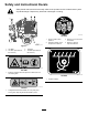
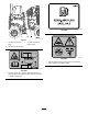
Safety and Instructional Decals Safety decals and instructions are easily visible to the operator and are located near any area of potential danger. Replace any decal that is damaged or missing. decal106-5976 106-5976 g037431 1. Engine coolant under pressure 3. Warning—do not touch the hot surface. 2. Explosion hazard—read the Operator's Manual. 4. Warning—read the Operator's Manual. Figure 3 1. 125-6688 2. 120-0627 (both sides of the machine) 3. 106-5976 4.
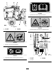
decal125-8483 125–8483 1. Hydraulic fluid; read the Operator’s Manual. g036698 Figure 4 1. 125-4963 2. 130-4291 decal125-6672 125–6672 3. 125-8483 4. 125-6672 1. Crushing hazard—stay away from articulated joints. decal125-4963 125-4963 1. Warning—do not touch hot surfaces. decal130-4291 g036696 130-4291 Figure 5 1. Regeneration inhibit—read the Operator's Manual. 1. 130-7360 2. 130-4341 3. 125-6674 6 4. 130-7361 5.
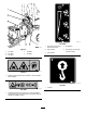
decal130-7361 130-7361 decal130-7360 130-7360 1. Raise the plow 3. Lower the trencher 2. Lower the plower 4. Raise the trencher 3. Engine—start 1. Engine—off ACK 130-4341 2. Engine—run/warming decal125-6680 125–6680 decal130-4341 130-4341 1. Regeneration acknowledge 1. Read the Operator’s Manual. 2. Turn left 4. Fast 3. Slow 6. Traction control 5. Turn right decal125-6674 125–6674 1. Disengage the parking brake. 2. Engage the parking brake. g036694 Figure 6 1. 133-8062 2.
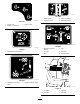
decal133-8062 133-8062 decal130-4340 130-4340 1. Fast 2. Engine speed 3. Slow decal130-4343 130-4343 1. Warning—read the Operator's Manual. 5. Warning—keep bystanders away. 2. Warning—do not operate the machine unless you have received instruction. 6. Warning—keep away from moving parts; keep all guards and shields in place. 3. Warning—wear a seatbelt. 7. Warning—do not operate the trencher while using the plow; do not operate the plow while using the trencher. 4. Warning—wear hearing 8.
decal125-6135 125–6135 g036695 Figure 7 1. 125-8487 (behind the step) 3. 125-8491 (behind the rubber guard) 2. 125-6135 (under the seat) decal125-8491 125–8491 1. Crushing hazard, warning—keep away from articulated joints; replace missing safety shields. decal125-8487 125–8487 1. Crushing hazard, tire—read the Operator’s Manual; the extension step must be attached when the tires are in wide or doubled configuration.
decal127-1822 127-1822 g036697 Figure 8 1. 127-1822 2. 125-4967 3. 125-6671 4. 125-6684 5. 125-6694 1. The engine cannot start with the plow active. 4. No vibration 2. High vibration 5. The engine can start with the plow inactive. 3. Low vibration decal125-6671 125-6671 1. Explosion hazard; electric shock hazard—call local utilities before digging. decal125-4967 125-4967 1. Lift point decal125-6684 125–6684 1.
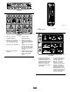
Controls Product Overview Become familiar with all of the controls before you start the engine and operate the machine. Throttle The throttle controls the engine speed. Push the knob to increase the engine speed. Pull the knob to decrease the engine speed. Parking-Brake Lever To set the parking brake, pull the lever up and push it forward. To release the parking brake, pull the lever back and down. Attachment Control Lever g025662 Figure 9 Right-side view 1. Vibratory plow 3. Engine-oil filter 5.
Creep-Control Lever Over time, ash accumulates in the DPF and a background regeneration is not sufficient to unclog the filter. When this occurs, the regeneration request and check engine lights illuminate on the control panel. At this time, the filter requires a stationary regeneration or needs to be serviced; contact your Authorized Service Dealer for more information. The creep-control lever controls the direction and speed of the machine while the attachments are in use.
off immediately and contact your Authorized Service Dealer for assistance. High-Temperature-Exhaust Indicator Charge Indicator This light illuminates when the DPF is undergoing regeneration. This light illuminates when the battery is being discharged. If the light illuminates during operation, shut off the machine, turn off the engine, and check for possible causes. Regeneration-Inhibit Indicator This light illuminates when automatic background regeneration has been turned off.
Fuel Safety Operation • Use extra care when handling fuel. It is flammable and its vapors are explosive. Note: Determine the left and right sides of the machine from the normal operating position. • Extinguish all cigarettes, cigars, pipes, and other sources of ignition. Before Operation • Use only an approved fuel container. • Do not remove the fuel cap or fill the fuel tank while the engine is running or hot. Before Operation Safety • Do not add or drain fuel in an enclosed space.
Biodiesel Ready Checking the Interlock System This machine can also use a biodiesel blended fuel of up to B20 (20% biodiesel, 80% petrodiesel). The petrodiesel portion should be low or ultra low sulfur. Observe the following precautions: Before using the machine, make the following interlock system checks. If any of these checks fails, contact your Authorized Service Dealer for more information. • The biodiesel portion of the fuel must meet specification ASTM D6751 or EN14214.
During Operation • During Operation Safety • General Safety • Do not exceed the rated operating capacity, as the • • • • • • • • • • • • • • • • • machine may become unstable, which may result in loss of control. Use only Toro-approved attachments and accessories. Attachments can change the stability and the operating characteristics of the machine. Use your full attention while operating the machine.
– Embankments – Bodies of water The machine could suddenly roll over if a tire goes over the edge or the edge caves in. Maintain a safe distance between the machine and any hazard. • Do not remove or add attachments on a slope. • Do not park the machine on a hillside or slope. Rotating the Wheels You can install the wheels to provide a narrow or a wide overall width of machine.
Shutting Off the Engine 1. Move the throttle lever to the SLOW position. 2. Lower any attachments to the ground. 3. Set all controls to the NEUTRAL position. 4. Set the parking brake. 5. Turn the ignition key to the OFF position. 5. Note: Do not start the plow vibration until the blade tip has entered the ground. Note: If the engine has been working hard or 6. Move the vibratory-plow lever to start the plow vibration. 7.
g025774 Figure 17 1. Snap-ring pin 2. Pin g021986 Figure 18 3. Pull the 2 pins out of the blade. 1. Nut 2. Washer 3. Skid shoes Note: The plow blades are heavy. Make sure that 1 person is holding the blade while the other person is removing the pins. 4. 4. Place the new blade into the plow blade assembly and secure it with 2 pins and 2 snap-ring pins. Raise the plow about 91 cm (36 inches) off the ground. 2. Shut off the engine and remove the key. 3.
Transporting the Machine Loading the Machine Important: Ensure that the trailer and ramp can support both your weight plus the weight of the machine with any attachments. 1. Start the engine. 2. Move the attachments to transport position. 3. Secure the trailer hitch to your vehicle and put a block at the front and rear of the trailer wheels. 4. Move the machine slowly onto the trailer. 5. Lower the attachments onto the trailer and set the parking brake. 6. Shut off the engine and remove the key.
Maintenance Note: Determine the left and right sides of the machine from the normal operating position. Download a free copy of the electrical or hydraulic schematic by visiting www.Toro.com and searching for your machine from the Manuals link on the home page. Important: Refer to your engine Operator's Manual for additional maintenance procedures. CAUTION If you leave the key in the ignition switch, someone could accidently start the engine and seriously injure you or other bystanders.
Maintenance Service Interval Every 100 hours Maintenance Procedure • • • • Check the battery electrolyte level (replacement battery only). Check the axle oil levels. Check the cooling system hoses. Check the hydraulic lines for leaks, loose fittings, kinked lines, loose mounting supports, wear, weather, and chemical deterioration. • Check for dirt build-up in the chassis.
Lubrication Greasing the Machine Service Interval: Before each use or daily (Grease immediately after every washing). Grease Type: General-purpose grease. 1. Clean the grease fittings with a rag. 2. Connect a grease gun to each fitting (Figure 22, Figure 23, and Figure 24. g026667 Figure 24 Underside view g021987 Figure 22 1. Grease fittings g023247 Figure 23 23 3. Pump grease into the fittings (approximately 3 pumps). 4. Wipe up any excess grease.
Engine Maintenance Engine Safety • Shut off the engine before checking the oil or adding oil to the crankcase. g026666 Figure 25 • Do not change the engine governor setting or overspeed the engine. • Keep your hands, feet, face, clothing, and other body parts away from the muffler and other hot surfaces. 1. Latch 2. Dust cap 5. Air filter 6. Safety filter 3. Gasket 7. Air-cleaner housing 4. Bracket 8. Dust valve Servicing the Air Cleaner 4.
Servicing the Engine Oil Service Interval: After the first 50 hours—Change the engine oil and filter. 1. Park the machine on a level surface, lower any attachments, shut off the engine, and remove the key. 2. Unlock the engine cover latches and open the engine cover. 3. Remove the dipstick, wipe it clean, install the dipstick into the tube, and pull it out again.
3. Remove the filler cap and the drain plug (Figure 28). g020436 Figure 29 1. Oil filter g025666 Figure 28 1. Oil-drain plug 4. Apply a thin layer of clean oil to the gasket seal of the new oil filter. 4. When the oil has drained completely, install the drain plug. 5. Apply a thin coat of the clean oil of the proper type through the center hole of the filter. Note: Dispose of the used oil at a certified 6.
Servicing the Diesel Particulate Filter (DPF) Fuel System Maintenance Service Interval: Every 3,000 hours DANGER Over time, ash accumulates in the DPF and a background regeneration is not sufficient to unclog the filter. When this occurs, the regeneration request and check engine lights illuminate on the control panel. At this time, the filter requires a stationary regeneration or needs to be replaced; contact your Authorized Service Dealer for more information.
Replacing the Fuel Filter Canister Electrical System Maintenance Service Interval: Every 500 hours—Replace the fuel filter/water separator. 1. Clean the filter head and the outside of the fuel filter. 2. Turn the filter counterclockwise and remove the filter from the filter head. 3. Lubricate the gasket on the new filter canister with clean oil. 4. Install the filter canister by hand until the gasket contacts the filter head, then rotate it an additional 1/2 turn. 5.
Charging the Battery Drive System Maintenance WARNING Charging the battery produces gasses that can explode. Servicing the Tires Never smoke near the battery and keep sparks and flames away from battery. Checking the Tires and Lug Nuts Important: Always keep the battery fully charged (1.265 specific gravity). This is especially important to prevent battery damage when the temperature is below 0°C (32°F). 1. Service Interval: Before each use or daily—Check the tire pressure.
Changing the Transmission Oil Servicing the Transmission and Axles Service Interval: Every 1,000 hours/Yearly (whichever comes first) 1. Park the machine on a level surface, lower any attachments, and shut off the engine. 2. Clean the area around the fill plug with a cleaning solvent (Figure 33). Transmission oil specification: SAE 80W140 API classification level GL5 Transmission oil capacity: approximately 0.47 L (0.
Cooling System Maintenance Note: The oil level should be even with the bottom of the fill plug hole. 4. Add oil to raise the oil level up to the bottom of the fill plug hole. 5. Install the fill plug. 6. Repeat for the other differential. Cooling System Safety • Swallowing engine coolant can cause poisoning; keep out of reach from children and pets. Changing the Axle Oil • Discharge of hot, pressurized coolant or touching 1. Place a drain pan under the pinion housing of the axle.
2. DANGER Check the coolant level in the radiator. Note: The radiator should be filled to the top of Rotating shaft and fan can cause personal injury. • Do not operate the machine without the covers in place. • Keep fingers, hands and clothing clear of rotating fan and drive shaft. • Shut off the engine and remove the ignition key before performing maintenance. the filler neck and the expansion tank filled to the Full mark (Figure 36). 3.
Belt Maintenance Replacing the Drive Belt Service Interval: Every 4,000 hours—Replace the alternator drive belt. Checking the Alternator Drive Belt Tension 1. Loosen the pivot bolts, the adjusting bolt, and move the alternator toward the engine to loosen the belt tension. 2. Remove the drive belt and install the new drive belt. 3. Adjust the belt tension to between 5 to 8 mm (3/16 to 5/16 inch) under load of 98 N-m (22 ft-lb). 4.
Controls System Maintenance The factory adjusts the controls before shipping the machine However, after many hours of use, you may need to adjust the controls. Important: To adjust the controls properly, complete each procedure in the order listed. Checking the Parking Brake Move the parking brake lever to the On position. If there is little or no resistance, complete the following procedure: 1. Park the machine on a flat surface, lower any attachments, shut off the engine, and remove the key. 2.
Hydraulic System Maintenance High Viscosity Index/Low Pour Point Anti-wear Hydraulic Fluid, ISO VG 46 Material Properties: Viscosity, ASTM D445 St @ 40° C 44 to 48 Hydraulic System Safety St @ 100° C 7.9 to 8.5 • Seek immediate medical attention if fluid is injected into skin. Injected fluid must be surgically removed within a few hours by a doctor.
8. Clean up any spilled fluid. 7. Install the cap on the filler neck. 9. Start the engine and let it run for about 2 minutes to purge any air from the system. 8. Close the hood. 10. Shut off the engine and check for leaks. Changing the Hydraulic Fluid Service Interval: After the first 250 hours Checking the Hydraulic-Fluid Level Every 1,000 hours/Yearly (whichever comes first) Service Interval: Before each use or daily 1. Position the machine on a level surface.
g026707 g026669 Figure 45 Figure 43 1. Hose clamp 9. 6. Remove the left side cover plate and loosen the 3 hose clamps under the hydraulic tank (Figure 44). 10. Flush the reservoir with cleaning solvent. Remove the elbow adapters and remove and clean the filter screens with compressed air (Figure 46). g026670 Figure 44 1. Hose clamp g026671 Figure 46 7. 8. Disconnect the electrical lead to the oil temperature sending unit at the bottom of the reservoir.
17. Start the engine and let it run for a few minutes. 18. Shut off the engine. 19. Check the hydraulic fluid level and top it off if necessary; refer to Checking the Hydraulic-Fluid Level (page 36). ROPS Maintenance Checking and Servicing the ROPS Checking the Hydraulic Lines Checking and Caring for the Seat Belt Service Interval: Every 100 hours—Check the hydraulic lines for leaks, loose fittings, kinked lines, loose mounting supports, wear, weather, and chemical deterioration.
Cleaning Removing Debris from the Machine Service Interval: Before each use or daily Important: Operating the engine with blocked screens and/or cooling shrouds removed, will result in engine damage from overheating. 1. Park the machine on a level surface, lower any attachments, and shut off the engine. 2. Remove the key and allow the engine to cool. 3. Open the hood. 4. Clean any debris from the front and side screens. 5. Wipe away any debris from the air cleaner. 6.
Storage Storage Safety • Shut off the engine, remove the key, wait for all moving parts to stop, and allow the machine to cool before storing it. • Do not store the machine or fuel near flames. Storage 1. Lower any attachments, shut off the engine, and remove the key. 2. Remove dirt and grime from the entire machine. Important: You can wash the machine with mild detergent and water. Do not pressure wash the machine.
Troubleshooting Problem The starter does not crank. Possible Cause 1. The controls are not in the neutral position. 1. Move all of the controls to the Neutral position. 2. The electrical connections are corroded or loose. 3. A fuse is blown or loose. 4. The battery is discharged. 5. The relay or switch is damaged. 2. Check the electrical connections for good contact. 3. Correct or replace the fuse. 4. Charge the battery or replace it. 5. Contact your Authorized Service Dealer. 6.
Problem The engine starts, but does not keep running. Possible Cause 1. The fuel tank vent is restricted. 1. Loosen the cap. If the engine runs with the cap loosened, replace the cap. 2. There is dirt or water is in the fuel system. 3. The fuel filter is clogged. 4. There is air in the fuel system. 2. Drain and flush the fuel system; add fresh fuel. 3. Replace the fuel filter. 4. Bleed the nozzles and check for air leaks at fuel hose connections and fittings between the fuel tank and engine. 5.
Problem The engine overheats. Possible Cause 1. More coolant is needed. 1. Check and add coolant. 2. There is restricted air flow to the radiator. 3. The crankcase oil level is incorrect. 4. The engine load is too excessive. 2. Inspect and clean the side panel screens with every use. 3. Fill or drain the oil to the full mark. 4. Reduce the load; use lower ground speed. 5. Drain and flush the fuel system; add fresh fuel. 6. Contact your Authorized Service Dealer. 7.
Problem The engine loses power. Possible Cause 1. The engine load is excessive. 1. Reduce the load; use lower ground speed. 2. The crankcase oil level is incorrect. 3. The air cleaner filters are dirty. 4. There is dirt, water, stale fuel, or incorrect fuel is in the fuel system. 5. The engine is overheating. 2. Fill or drain to the full mark. 3. Service the air filters. 4. Drain and flush the fuel system; add fresh fuel. 5. Refer to troubleshooting item The engine is overheating. 6.
Notes:
Notes:
California Proposition 65 Warning Information What is this warning? You may see a product for sale that has a warning label like the following: WARNING: Cancer and Reproductive Harm—www.p65Warnings.ca.gov. What is Prop 65? Prop 65 applies to any company operating in California, selling products in California, or manufacturing products that may be sold in or brought into California.