
Operator's Manual

3
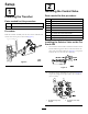
InstallingtheTrencherLever
andValve
Partsneededforthisprocedure:
2
Nut(3/8inch/ProSneak360)
2
Switchassembly(ProSneak360)
1
Cover(ProSneak360)
1
ProSneak360valvebracket
1
Linkassembly(ProSneak360)
1
Bolt(5/16x2-1/4inches/ProSneak360)
2
Bolt(3/8inch/ProSneak360)
5
Bolt(5/16x1inch/ProSneak360)
1
Bolt(5/16x2-1/2inches/ProSneak360)
8
Washer(5/16inch/ProSneak360)
4
Washer(3/8inch/ProSneak360)
1
Cotterpin(ProSneak360)
1
Nut(ProSneak360)
2
Locknut(ProSneak360)
1
Valvelever(ProSneak360)
1
Rodswitch(ProSneak360)
5
U-Nut(5/16inch/ProSneak360)
1
Clevispin(ProSneak360)
1
Balljoint(ProSneak360)
1
ProSneak360Valve
4
90-degreeelbowtting
3
45-degreeelbowtting
1
ProSneak365valve
1
ProSneak365bracket
1
ProSneak365switch
3
Bolts(5/16x1-1/4inch/ProSneak365)
3
Nuts(5/16x1-1/4inch/ProSneak365)
1
Handleassembly(ProSneak365)
1
Longstraighttting(ProSneak365)
2
Shortstraighttting(ProSneak365)
InstallingtheTrencherSwitchand
ValveAssemblyontheProSneak360
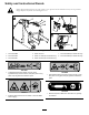
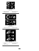
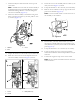
1.InstallthettingsasshowninFigure11.
2.Torquethettingsontheportsideto104to127N-m
(77to94ft-lb).
1
2
g023172
1
2
Figure11
1.45-degreeelbowtting2.90-degreeelbowtting
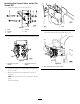
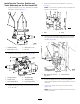
3.Securethevalvetothebracketusing2bolts(5/16x
2-1/4and5/16x2-1/2inch),2washers(5/16inch),
and2locknuts(Figure12).
1
2
g023092
Figure12
1.Bolt(5/16x2-1/4inch)2.Bolt(5/16x2-1/2inch)
4.Torquethefastenersto31to37N-m(270to330in-lb).
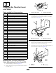
5.Placetheleverinbetweentheguidesonthebracket
andsecurewiththeclevisandcotterpin.
6.Securethelevertothevalveusingthelinkassemblyon
thebottomholeofthelever(Figure13).
1
2
g023176
3
4
Figure13
1.Clevispin
3.Nut
2.Cotterpin
4.Linkassembly
8