
Operator's Manual
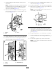

7.Attachtheballjointandswitchrodonthetophole
ofthelever.
Note:Assembletherodsothattheswitchassemblyis
centeredbetweentheForwardandReversepositions.
Addthreadlockingadhesivetothenutandtighten
ontotherodassembly(Figure13).
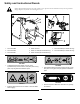
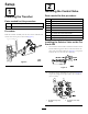
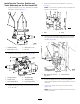
8.Securetheswitchassemblytothebracketusingthe2
bolts(5/16inch),2washers(5/16inch),and2U-nuts
(5/16inch)(Figure14).
3
1
2
g023177
Figure14
1.Washer3.U-nut
2.Bolt
9.Torquethefastenersto19to25N-m(175to225in-lb).
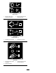
10.PlacetheU-nutsontothecoverandplacethecover
ontotheassemblyasshowninFigure15;BoxA.
Figure15
1.Cover3.Botls(5/16inch)
2.U-nuts
11.Securethecovertotheassemblywiththe3bolts(5/16
inch)asshowninFigure15;boxB.
12.Torquethefastenersto19to25N-m(175to225in-lb).
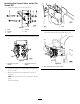
13.Removethenutandboltonthetoprightoftheaccess
panelonthemachine(Figure16).
Note:Usetheboltandwashertosecurethecoverof
theassemblytothemachine.
g023175
Figure16
14.Insert2bolts(3/8inch)and2washers(3/8inch)
throughtheassemblyandsecurewith2washers(3/8
inch)and2nuts(3/8inch)ontheinsideofthemachine
panel(Figure16).
15.Torquethefastenersto37to45N-m(27to33ft-lb).
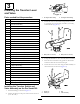
16.Locatethesinglewirelooponthewiringharness
locatedinthemachinenearthesidepanelthatwasjust
removed.
17.Connectthesinglewirelooptothesensorswitch.
Note:Donotoperatethemachinewithoutthesensor
switchattached.
9