Form No. 3389-744 Rev A Trencher Drive Pro Sneak 360 and 365 Vibratory Plow Model No. Model No. Model No. Model No. Register at www.Toro.com. Original Instructions (EN) 25410—Serial No. 313000001 and Up 25410E—Serial No. 313000001 and Up 25411—Serial No. 314000001 and Up 25411E—Serial No.
1 WARNING CALIFORNIA Proposition 65 Warning This product contains a chemical or chemicals known to the State of California to cause cancer, birth defects, or reproductive harm. g019163 DANGER Figure 1 There may be buried power, gas, and/or telephone lines in the work area. A shock or an explosion may occur if you dig into them. 1. Model and serial number location Have the property or work area marked for buried lines and do not dig in marked areas.
Contents Safety Safety ........................................................................... 3 Safety and Instructional Decals ................................. 4 Setup ............................................................................ 6 1 Installing the Trencher........................................... 6 2 Installing the Control Valve .................................... 6 3 Installing the Trencher Lever and Valve .................... 7 4 Installing the Hydraulic Hoses .................
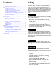
Safety and Instructional Decals Safety decals and instructions are easily visible to the operator and are located near any area of potential danger. Replace any decal that is damaged or lost. B A 6 5 C 7 8 g025483 Figure 3 1. Decal 125-6686 4. Decal 125-8175 7. Decal 125-6676 (Pro Sneak 360 only) 2. Decal 125-6670 5. Decal 127-1826 (Pro Sneak 365 only) 8. Decal 125-6678 (Pro Sneak 360 only) 3. Decal 125-6671 6. Decal 125-6678 (Pro Sneak 365 only) 125–6670 125–6686 1.
127-1826 Model 25411 1. Move the lever up to control the trencher. 2. Move the lever down to control the plow. 125–6676 Model 25410 only 1. Raise/lower the trencher. 2. Raise/lower the plow. 125–6678 1. Turn the trencher chain clockwise. 2. Stop the trencher. 3. Turn the trencher chain counterclockwise.
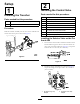
Setup 2 1 Installing the Control Valve Parts needed for this procedure: Installing the Trencher Parts needed for this procedure: 4 Bolt (3/8 x 3–1/4 inch) 8 Washer (3/8 inch) 1 Trencher assembly 4 Nut (3/8 inch) 2 Clevis pin 1 Pro Sneak 360 control valve 1 Pro Sneak 365 control valve 1 Pro Sneak 360 control-valve bracket 1 Pro Sneak 365 control-valve bracket 8 90-degree short drop adaptor 4 90-degree long drop adaptor Procedure Slide the trencher assembly into the slots on the mac
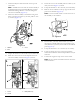
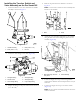
Installing the Control Valve on the Pro Sneak 365 1 2 1. Attach the bracket to the valve (Figure 7). 1 2 3 4 5 g025477 Figure 9 g025479 1. Bolts Figure 7 1. Bolts 2. Bracket 3. Valve 4. Washers 5. Nuts 2. Panel 5. Attach the bracket to the machine using the bolts previously removed from the panel (Figure 10). 2. Attach the valve fittings to the valve as shown in Figure 8. 1 2 1 2 g025478 Figure 8 1. 90-degree long drop adapter g025480 2. 90-degree short drop adapter Figure 10 1.
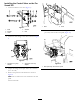
2 3 1 Installing the Trencher Lever and Valve 1 g023172 2 Figure 11 Parts needed for this procedure: 1. 45-degree elbow fitting 2.
7. Attach the ball joint and switch rod on the top hole of the lever. 11. Secure the cover to the assembly with the 3 bolts (5/16 inch) as shown inFigure 15; box B. 12. Torque the fasteners to 19 to 25 N-m (175 to 225 in-lb). Note: Assemble the rod so that the switch assembly is centered between the Forward and Reverse positions. Add thread locking adhesive to the nut and tighten onto the rod assembly (Figure 13). 13.
Installing the Trencher Switch and Valve Assembly on the Pro Sneak 365 4. Remove the panel from the machine as shown in Figure 19. Note: Use the bolts to attach the valve assembly and bracket to the machine. 1. Attach the bracket to the valve and attach the handle assembly as shown in Figure 17. 1 1 2 2 4 g025486 Figure 19 1. Bolts 2. Panel 5. Attach the valve assembly and bracket to the machine using the bolts that were holding the panel onto the machine (Figure 20). 3 g025488 Figure 17 1.
4 Installing the Hydraulic Hoses Parts needed for this procedure: 1 90-degree adapter fitting (Pro Sneak 365) 3 90-degree fitting (Pro Sneak 365) 1 Straight fitting (Pro Sneak 365) 6 Cable ties 1 Hydraulic tube 1 Hydraulic tube cap 2 Hose (15 inches) 4 Hose (82 inches) 2 Hose (88 inches) 1 Hose (28 inch / Pro Sneak 365) 1 Hose (36 inches / Pro Sneak 360) 1 Hose (80 inches / Pro Sneak 360) 1 Hose (21 inches / Pro Sneak 360) 1 Hose (18 inches / Pro Sneak 360) 1 Hose (26 inches / P
1 3 2 5 4 16. Connect the 31-inch hose to port A on the control valve to port B on the attachment lift (Figure 24). 6 17. Torque the hose fittings to 27 to 32 N-m (20 to 24 ft-lb). 18. Connect the 88-inch hose to port C3 on the control valve, the bottom hole closest to the handle, to port A on the hydraulic cylinder assembly (Figure 25). 7 g023089 Figure 23 1. Port A 2. Plow lift cylinder 5. Port C1 6. Port C2 3. Attachment lift 4. Control valve 7. Port B 11.
Installing the Hydraulic Hoses on the Pro Sneak 365 1 2 3 4 5 6 1. Remove the hose that is currently installed onto the first port of the hydraulic gear pump, add a 90-degree connector to the hose fitting, and connect the hose and connector to the 15-inch hose (Figure 26). 1 2 3 4 5 6 g025491 Figure 27 g025492 1. Valve 4. 90-degree swivel adaptor fitting 2. Hose (82 inch) 5. Straight fitting 3. Hose (82 inch) 6. Hydraulic motor assembly Figure 26 1. Hose (15 inch) 4.
17. Connect 1 of the 88-inch hoses to the inside fitting on the bottom row of the control valve (port C3) to the bottom of the hydraulic cylinder assembly using a 90-degree fitting (Figure 30). 13. Remove the 2 hoses that are connected to the under side of the bulkhead plate located behind the panel that was removed from the machine and attach them to the fittings on the middle row of the valve as shown in Figure 29. 1 1 2 4 3 3 2 4 g025484 Figure 29 1. Valve 2. Hose 3. Attachment lift valve 4.
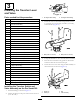
10. Loop the digging chain over the auger drive shaft and onto the drive sprocket, ensuring that the digging teeth point forward on the upper span. 5 11. Set the upper span of the chain into place on the trencher boom, then wrap the chain around the roller at the end of the boom. Installing the Boom and Digging Chain (Sold separately) Refer to Servicing the Trencher Digging Chain (page 22) to adjust the chain tension.
1 2 3 4 7 5 g023163 8 6 Figure 34 g019092 Figure 35 ProSneak 360 7 1. Throttle 5. Parking brake 2. PTO 3. Creep control 6. Attachment control lever 7. Trencher control lever 4. Directional control lever 8. Attachment selector lever Testing the Installation 1 Parts needed for this procedure: 1 2 3 Trencher boom and chain kit Procedure Use the following procedure to test the operation of the machine.
Product Overview 7. Pull the trencher control lever toward you (Figure 36). The trencher should rotate backward in a counterclockwise direction, pulling the teeth back toward the machine along the top of the trencher boom. Specifications Note: Specifications and design are subject to change without notice. 8. With the trencher running, stand up, removing your weight from the operator seat. The engine should stop within 1 second.
Operation 1 Refer to your traction unit Operator’s Manual for more information on installing and removing attachments on your traction unit. Important: Always use the machine to lift and move the attachment. G027097 Figure 37 Selecting the Proper Components for the Trencher 1. Cupped teeth Using the correct trencher components helps to increase the trenching speed and extending the life of the trencher. Contact an Authorized Toro Service Dealer for more information on parts for your trencher.
Combinations of Boom, Chain, and Teeth for Various Soil Types and Conditions Boom Type Soil Type Sprocket Boom Rock Boom Digging Teeth Type Chain Type Standard Chain HD ABF H-Plate Cup Cutter Sand X X X Sandy Loam X X X Loose Shale X X X Topsoil X X X X X Caliche (Hard) X Clay (Gumbo) X X X X Rock/Frost Mining Bit Mixed Shark X X X X Coral X X X X X Rock (Loose) X X X X X Asphalt X X X X X Hard Clay X X X X X X Frozen Soil X X X X X X No
1 Operating Tips 2 • Clean the area of trash, branches, and rocks before 3 digging to prevent damage to the equipment. • Always begin digging with the slowest ground speed possible. Increase the speed if conditions allow for safe operation. • Always use full throttle (maximum engine speed) when trenching. • Always trench backwards (i.e., in reverse). • Trench at a 45 to 60-degree angle for best results. 5 • If the trencher binds in the soil, stop the machine and 4 reverse the chain direction.
Maintenance Recommended Maintenance Schedule(s) Maintenance Service Interval Maintenance Procedure After the first 8 hours • Check the chain tension. Before each use or daily • Grease the trencher. • Check the chain tension. Every 25 hours • Adjust the trencher drive chain. Before storage • Grease the trencher. • Paint chipped surfaces. • Check the sensor switch; adjust as needed.
Increasing the Chain Tension Servicing the Trencher Digging Chain Grease Type: Lithium-based grease 1. Remove the top access cover plate on the trencher boom to access the piston (Figure 45). Checking the Chain Tension Service Interval: After the first 8 hours Before each use or daily 1 1. Start the engine and make a trench about 3 m (10 ft) long. 2. Stop the trencher chain and lift the boom out of the trench. 3. Move the boom to the horizontal position . 2 1 2 g023235 Figure 45 3 1.
Checking and Adjusting the Sensor Switch (ProSneak 360 only) Adjusting the Trencher Drive Chain Service Interval: Monthly Important: Do not over-tighten the chain. Excess chain tension may damage drive components. Service Interval: Every 25 hours 1. Measure the gap in between the back of the sensor and the bracket. The gap should be 0.3175 cm (0.125 inch). 1. Remove the chain guard from the trencher. 2.
Storage 1. Before long term storage, brush the dirt from the attachment. 2. Check the condition of the digging chain. Adjust and lubricate the chain. Replace any worn or damaged teeth. 3. Check and tighten all bolts, nuts, and screws. Repair or replace any part that is damaged or worn. 4. Ensure that all hydraulic couplers are connected together to prevent contamination of the hydraulic system. 5. Paint all scratched or bare metal surfaces. Paint is available from your Authorized Service Dealer. 6.
Troubleshooting Problem The chain does not turn. Possible Cause Corrective Action 1. A hydraulic coupler is not completely connected. 1. Check and tighten all couplers. 2. A hydraulic coupler is damaged. 3. There is an obstruction in a hydraulic hose 4. An auxiliary valve on the machine is not opening. 5. The boom end bearing failed. 6. The digging chain is too tight. 7. There is sand buildup in tooth root of the drive sprocket. 2. Check/replace the coupler(s). 3. Find and remove the obstruction. 4.
Notes: 26
Notes: 27
Toro Compact Utility Equipment Warranty Compact Utility Equipment (CUE) Products A One-Year Limited Warranty Conditions and Products Covered Items and Conditions Not Covered The Toro Company and its affiliate, Toro Warranty Company, pursuant to an agreement between them, jointly warrant your Toro Compact Utility Equipment (“Product”) to be free from defects in materials or workmanship.