
Operator's Manual
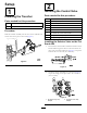

InstallingtheTrencherSwitchand
ValveAssemblyontheProSneak365
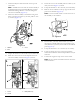
1.Attachthebrackettothevalveandattachthehandle
assemblyasshowninFigure17.
1 2
4
3
g025488
Figure17
1.Handleassembly
3.Nuts(5/16x1-1/4)
2.Bolts(5/16x1-1/4)
4.Hexnut
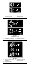
2.Attachthevalvettingstothevalve(Figure18).
5
6
1
2
3
g025487
4
Figure18
1.90-degreetting4.90-degreetting
2.Sensorswitch5.45-degreetting
3.Shortstraighttting6.Longstraighttting
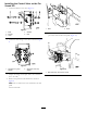
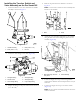
3.Torquethettingsontheportsideto104to127N-m
(77to94ft-lb).
4.Removethepanelfromthemachineasshownin
Figure19.
Note:Usetheboltstoattachthevalveassemblyand
brackettothemachine.
1
2
g025486
Figure19
1.Bolts2.Panel
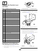
5.Attachthevalveassemblyandbrackettothemachine
usingtheboltsthatwereholdingthepanelontothe
machine(Figure20).
g025489
1 2
Figure20
1.Boltspreviouslyremoved
frompanel
2.Valveassembly
6.Locatethesinglewirelooponthewiringharness
locatedinthemachinenearthesidepanelthatwasjust
removed.
7.Connectthesinglewirelooptothesensorswitch
(Figure18).
Note:Donotoperatethemachinewithoutthesensor
switchconnected.
10