
Operator's Manual

Setup
1
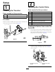
InstallingtheTrencher
Partsneededforthisprocedure:
1Trencherassembly
2
Clevispin
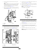
Procedure
Slidethetrencherassemblyintotheslotsonthemachineand
securewithaclevispinoneachside(Figure4).
g023233
Figure4
2
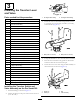
InstallingtheControlValve
Partsneededforthisprocedure:
4
Bolt(3/8x3–1/4inch)
8
Washer(3/8inch)
4
Nut(3/8inch)
1
ProSneak360controlvalve
1
ProSneak365controlvalve
1
ProSneak360control-valvebracket
1
ProSneak365control-valvebracket
890-degreeshortdropadaptor
490-degreelongdropadaptor
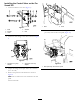
InstallingtheSelectorValveonthePro
Sneak360
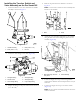
1.Insert2boltsand2washersinsidethetrencherswitch
bracketandthroughtheselectorvalveandsecurethe
valveusing2washersand2nuts(Figure5);torquethe
fastenersto51to65N-m(38to48ft-lb).
g023174
Figure5
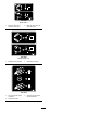
2.InstallthettingsandadaptorsasshowninFigure6;
torquethettingsontheportsideto36to44N-m
(27to33ft-lb).
g023173
2
1
2
Figure6
1.90-degreelongdrop
adapter
2.90-degreeshortdrop
adapter
6