
Operator's Manual


g021922
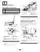
Figure4
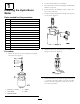
8.Securethemotorassemblytothemachineusing2
bolts(1/2x1-3/4inch),2atwashers(1/2inch),and
2locknuts(1/2inch);torqueto142N-m(105ft-lb).
(
Figure5).
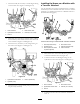
g021923
Figure5
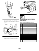
9.Installthejointassemblytothemotorassembly.Secure
withthebolt(3/8inch)andthenut(3/8x2-1/2inch)
(Figure6);torqueto55to63N-m(40to45ft-lb).
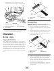
g021924
Figure6
2
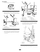
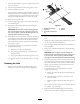
InstallingtheControlValve
andHandle
Partsneededforthisprocedure:
1Bracket
1
Controlvalve
1
90-degree,elbowtting
2
45-degree,elbowtting
1
Straighttting
2
Bolt(3/8x1inch)
4
Flatwasher(3/8inch)
2
Nut(3/8inch)
1
Bolt(5/16x2-1/2inch)
1
Bolt(5/16x2-1/4inch)
2
Flatwasher(0.344inch)
2
Locknut(5/16inch)
1
Clevispin
1
Cotterpin
1
Controllever
1Linkassembly
1
Snapclip
4