
Operator's Manual


Procedure
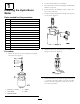
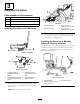
1.InstallthettingsasshowninFigure7.
g021925
Figure7
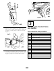
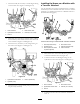
2.Installthebracketandsecurewiththe2nuts(3/8
inch),the2washers(3/8inch),andthe2bolts(3/8
inch)(Figure8);torqueto38to43N-m(28to32ft-lb).
1
2
3
g021926
Figure8
1.Nut(3/8inch)3.Bolt(3/8inch)
2.Flatwasher(3/8inch)
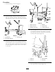
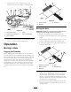
3.Installthecontrolvalveontothebracketandsecure
withthe2bolts(5/16x2-1/4inchand5/16x2-1/2
inch),the2atwashers(0.344inch)andthe2locknuts
(5/16inch)(Figure9);torqueto32to35N-m(280
to310in-lb).
5
2
3
4
g021927
1
6
Figure9
1.Bolt(2-1/4inch)
4.Bracket
2.Bolt(2-1/2inch)5.Controlvalve
3.Washer(0.344inch)6.Locknut(5/16inch)
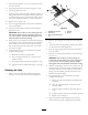
4.Placethehydra-borer-controlleverbetweentheguide
onthebracketattachedtothemachinesothatthe
holeslineup.Securethecontrolleverwiththelink
assemblyandsnapclip(Figure10).
1
2
3
g021928
4
Figure10
1.Cotterpin
3.Linkassembly
2.Clevispin4.Snapclip
5.Securetheupperholeofthecontrolleverwiththe
clevispinandthecotterpin(Figure10).
5