
Operator's Manual

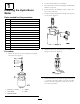
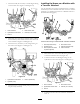

1.ConnecthoseB(14.74inches)tothe90-degreetting
onthecontrolvalve(Figure11andFigure14).
1
2
4
g021983
3
5
Figure14
1.Hoseconnector4.Plow-controlvalve
2.Hydra-borer-controlvalve
5.HoseB(14.74inches)
3.HoseA
2.DisconnecthoseAfromthehydraulicpump,addthe
hoseconnector,andconnecthoseBtotheotherend
oftheconnector(Figure13andFigure14).
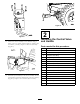
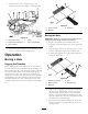
3.ConnecthoseC(36inches)tothestraightttingon
thecontrolvalve(Figure11andFigure15).
1
g021984
3
2
Figure15
1.Hydra-borer-controlvalve
3.HoseC(36inches)
2.Hydraulicpump
4.ConnecthoseCtothehydraulicpump(wherehoseA
waspreviouslyattached).
InstallingtheHosesonaMachinewith
aTrencherAttached
Usethisprocedureifyouhaveamachinethathasatrencher
attached.Ifyouhaveamachinethatdoesnothaveatrencher
attached,gotoInstallingtheHosesonaMachinewithouta
TrencherAttached(page6).
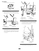
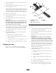
Figure16
Currenthoseroutingonamachinewithatrencherinstalled.
1.HoseE(trencherhose)
4.Plow-controlvalve
2.Hydraulicpump
5.HoseD(trencherhose)
3.HoseA(sameashoseA
inpreviousgures)
6.Hoseconnector
1.DisconnecthoseAfromhoseD,leavingthehose
connectorattachedtohoseA(Figure16).
2.ConnecthoseBtothe90-degreettingonthe
hydra-borer-controlvalve(Figure11andFigure17).
1
2
4
g021983
3
5
Figure17
1.Hoseconnector4.Plow-controlvalve
2.Hydra-borer-controlvalve
5.HoseB(14.74inches)
3.HoseA
3.ConnecthoseBtothehoseconnectorattachedto
hoseA.
7