
Operator's Manual

5
2
3
4
g021927
1
6
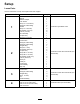
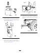
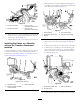
Figure9
1.Bolt(2-1/4inch)
4.Bracket
2.Bolt(2-1/2inch)5.Controlvalve
3.Washer(0.344inch)6.Locknut(5/16inch)
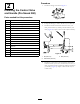
5.Placethehydra-borer-controlleverbetweentheguide
onthebracketattachedtothemachinesothatthe
holeslineup.Securethecontrolleverwiththelink
assemblyandsnapclip(Figure10).
1
2
3
g021928
4
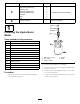
Figure10
1.Cotterpin
3.Linkassembly
2.Clevispin4.Snapclip
6.Securetheupperholeofthecontrolleverwiththe
clevispinandthecotterpin(Figure10).
3
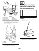
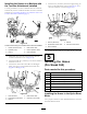
InstallingtheControlValve
andHandle(ProSneak365)
Partsneededforthisprocedure:
1Bracket
1
Controlvalve
2
45-degree,elbowtting
3
Straighttting
3
Bolt(11/4inch)
3Nut
1Handleassembly
Procedure
1.Attachthebrackettothevalveusingthe3boltsand3
nutsshowninFigure11.
g025904
Figure11
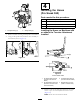
2.AttachthettingstothevalveasshowninFigure12
andtorqueto104to127N-m(77to94ft-lb).
7