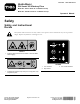
Form No. 3377-939 Rev B Hydra Borer Pro Sneak 360 Vibratory Plow Model No. 25418—Serial No. 313000001 and Up Model No. 25418E—Serial No. 313000001 and Up Operator's Manual Safety Safety and Instructional Decals Safety decals and instructions are easily visible to the operator and are located near any area of potential danger. Replace any decal that is damaged or lost. 125-6671 1. Explosion hazard; electric shock hazard—call local utilities before digging. 125–8488 1. Turn clockwise 2.
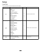
Setup Loose Parts Use the chart below to verify that all parts have been shipped. Procedure 1 2 3 Description Use Qty. Motor Adapter Retainer adapter Lock washer Bolt (1/2 x 1-1/4 inches) 90-degree, elbow fitting Hose, 114.
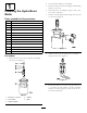
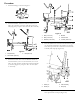
2. Put the retainer adapter on the adapter. 1 3. Place the washer on the bolt and apply thread-locking adhesive to the bolt. 4. Secure the bolt to the adapters; torque to 160 to 165 N-m (118 to 122 ft-lb). Installing the Hydra Borer Motor 5. Install 2 of the 90-degree, elbow fittings into the ports on the motor (Figure 2). Parts needed for this procedure: 1 Motor 1 Adapter 1 Retainer adapter 1 Lock washer 1 Bolt (1/2 x 1-1/4 inches) 2 90-degree, elbow fitting 2 Hose, 114.
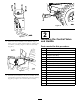
g021924 Figure 6 2 g021922 Figure 4 Installing the Control Valve and Handle 8. Secure the motor assembly to the machine using 2 bolts (1/2 x 1-3/4 inch), 2 flat washers (1/2 inch), and 2 locknuts (1/2 inch); torque to 142 N-m (105 ft-lb). (Figure 5). Parts needed for this procedure: g021923 Figure 5 9. Install the joint assembly to the motor assembly. Secure with the bolt (3/8 inch) and the nut (3/8 x 2-1/2 inch) (Figure 6); torque to 55 to 63 N-m (40 to 45 ft-lb).
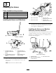
Procedure 1 1. Install the fittings as shown in Figure 7. 2 3 g021925 Figure 7 4 2. Install the bracket and secure with the 2 nuts (3/8 inch), the 2 washers (3/8 inch), and the 2 bolts (3/8 inch) (Figure 8); torque to 38 to 43 N-m (28 to 32 ft-lb). 5 6 g021927 Figure 9 1 2 3 1. Bolt (2-1/4 inch) 4. Bracket 2. Bolt (2-1/2 inch) 5. Control valve 3. Washer (0.344 inch) 6. Locknut (5/16 inch) 4.
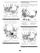
3 3 Installing the Hoses 4 2 Parts needed for this procedure: 2 Hose, 114.3 cm (45 inches) 1 Hose, 91.44 cm (36 inches) 1 Hose, 37.44 cm (14.74 inches) 1 Hose connector g021980 1 Figure 12 Installing the Hoses on all Machines 1. Port A on the motor 3. Port A on the hydra-borer-control valve 2. Port B on the motor 4. Port B on the hydra-borer-control valve 2. Route the other 114.
1. Connect hose B (14.74 inches) to the 90-degree fitting on the control valve (Figure 11 and Figure 14). Installing the Hoses on a Machine with a Trencher Attached 2 Use this procedure if you have a machine that has a trencher attached. If you have a machine that does not have a trencher attached, go to Installing the Hoses on a Machine without a Trencher Attached (page 6). 1 3 4 g021983 5 Figure 14 1. Hose connector 2. Hydra-borer-control valve 4. Plow-control valve 5. Hose B (14.74 inches) 3.
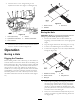
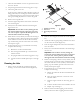
4. Connect hose C to the straight fitting on the hydra-borer-control valve (Figure 11 and Figure 18). 2 1 4 5 3 Figure 19 1. Entrance trench 2. Sidewalk 3. Exit trench Boring the Hole g021985 Figure 18 1. Hose C (36 inches) 4. Hose D 2. Hydra-borer-control valve 5. Trencher-control valve Important: Boring is a two person operation. Do not attempt to perform this operation by yourself. 1.
7. Once the entire drill bit is in the soil, push the control lever into neutral. 8. Stop the engine and wait for all moving parts to stop. 9. Check the grade of the rod. If the rod is not within the grade tolerances for the job being performed, start the engine, and drive backward to pull the boring bit out of the soil, then repeat steps 5 through 9, making adjustments to correct the grade. 10. Remove the rod guide tool. 11. Start the engine and pull the control lever rearward to start the boring bit. 12.
Storage 1. Before long term storage, wash the attachment with mild detergent and water to remove dirt and grime. 2. Check the condition of the hydraulic hoses. Replace any damaged hoses. 3. Ensure that all hydraulic couplers are connected together to prevent contamination of the hydraulic system. 4. Check and tighten all bolts, nuts, and screws. Repair or replace any damaged or worn part. 5. Paint all scratched or bare metal surfaces. Paint is available from your Authorized Service Dealer. 6.
Troubleshooting Problem The bore drive head will not rotate. Possible Cause Corrective Action 1. The hydraulic coupler is not completely connected. 1. Check and tighten all couplers. 2. A hydraulic coupler is damaged. 2. Check the couplers and replace any that are damaged. 3. Find and remove the obstruction. 3. There is an obstruction in a hydraulic hose. 4. A hydraulic hose is kinked. 5. The auxiliary valve on the machine is not opening. 6. A hydraulic motor is damaged or worn. 11 4.
Astec Brand Product Sold after November 1, 2012 The Toro Underground Warranty A Limited Warranty Conditions and Products Covered The Toro Company and its affiliate, Toro Warranty Company, pursuant to an agreement between them, jointly warrant your Toro Underground product (“Product”) to be free from defects in materials or workmanship. Where a warrantable condition exists, we will repair the Product at no cost to you including diagnostics, labor, and parts.