
Operator's Manual

3
InstallingtheHoses
Partsneededforthisprocedure:
2
Hose,114.3cm(45inches)
1
Hose,91.44cm(36inches)
1
Hose,37.44cm(14.74inches)
1Hoseconnector
InstallingtheHosesonallMachines
1
2
3
4
1
3
g021979
2
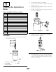
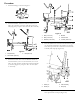
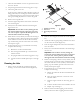
Figure11
ControlValveViews
1.45-degreetting(B
port/45-inchhosefrom
Motor)
3.45-degreetting(A
Port/45-inchhosefrom
Motor)
2.90-degreetting(HoseB
(14.74-inchhose)toPlow
Valve)
4.Straighttting(Hose
C/36-inchhose)
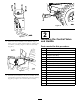
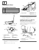
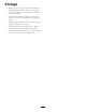
1.Routea114.3cm(45inch)hosefromportAonthe
motortoportAonthehydra-borer-controlvalve
(
Figure12).
Note:Routethehosesundertheframe.
g021980
1
2
3
4
Figure12
1.PortAonthemotor3.PortAonthe
hydra-borer-controlvalve
2.PortBonthemotor4.PortBonthe
hydra-borer-controlvalve
2.Routetheother114.3cm(45inch)hosefromportB
onthemotortoportBonthehydra-borer-control
valve(Figure11andFigure12).
InstallingtheHosesonaMachine
withoutaTrencherAttached
Usethisprocedureifyouhaveamachinethatdoesnothave
atrencherattached.Ifyouhaveamachinehastrencher
attached,gotoInstallingtheHosesonaMachinewitha
TrencherAttached(page7).
2
g021981
1
3
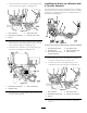
Figure13
Currenthoserouting
1.HydraulicPump3.Plow-controlvalve
2.HoseA(currentlyinstalled
onthemachine)
6