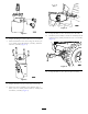
Form No. 3389-762 Rev A Hydra Borer Pro Sneak 360 or 365 Vibratory Plow Model No. 25418 Model No. 25418E Model No. 25421 Model No. 25421E Operator's Manual WARNING CALIFORNIA Proposition 65 Warning This product contains a chemical or chemicals known to the State of California to cause cancer, birth defects, or reproductive harm. Safety Safety and Instructional Decals Safety decals and instructions are easily visible to the operator and are located near any area of potential danger.
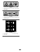
125-6671 1. Explosion hazard; electric shock hazard—call local utilities before digging. 125–6681 1. Entanglement hazard—keep away from moving parts; keep all guards in place. 125–8488 1. Turn clockwise 2. Stop rotation 3.
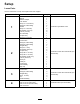
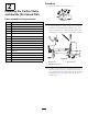
Setup Loose Parts Use the chart below to verify that all parts have been shipped. Procedure 1 2 3 4 Description Qty.
Procedure Description Use Qty. 5 Hose, 51 cm (20 inches) Hose, 95 cm (38 inches) Hydraulic tube 90 degree adapter fitting 45 degree adapter fitting R-clamps Bolts Nuts 1 2 3 1 2 2 2 2 Install the hoses (Pro Sneak 365). 6 No parts required – Test the installation.
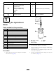
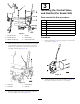
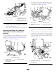
g021923 Figure 5 g021920 10. Torque the bolts to 91 to 113 N-m (67 to 83 ft-lb). Figure 3 11. Install the joint assembly to the motor assembly. Secure with the bolt (3/8 inch) and the nut (3/8 x 2-1/2 inch) (Figure 6). 6. Torque the fittings to 104 to 127 N-m (77 to 94 ft-lb). 7. Secure the bracket to the motor using the 4 bolts (1/2 x 1 3/4 inch), the 4 flat washers (1/2 inch), and the 4 locknuts (1/2 inch) (Figure 4). g021924 Figure 6 12. Torque the bolts to 55 to 63 N-m (40 to 45 ft-lb).
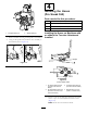
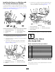
Procedure 2 1. Install the fittings as shown in Figure 7. Installing the Control Valve and Handle (Pro Sneak 360) Parts needed for this procedure: 1 Bracket 1 Control valve 1 90-degree, elbow fitting 2 45-degree, elbow fitting 1 Straight fitting 2 Bolt (3/8 x 1 inch) 4 Flat washer (3/8 inch) 2 Nut (3/8 inch) 1 Bolt (5/16 x 2-1/2 inch) 1 Bolt (5/16 x 2-1/4 inch) 2 Flat washer (0.
3 1 Installing the Control Valve and Handle (Pro Sneak 365) 2 3 Parts needed for this procedure: 4 5 6 g021927 Figure 9 1 Bracket 1 Control valve 2 45-degree, elbow fitting 3 Straight fitting 3 Bolt (1 1/4 inch) 3 Nut 1 Handle assembly 4. Bracket 1. Bolt (2-1/4 inch) 2. Bolt (2-1/2 inch) 5. Control valve 3. Washer (0.344 inch) 6. Locknut (5/16 inch) Procedure 1. Attach the bracket to the valve using the 3 bolts and 3 nuts shown in Figure 11. 5.
4 Installing the Hoses (Pro Sneak 360) 1 Parts needed for this procedure: g025905 2 2 Hose, 114.3 cm (45 inches) 1 Hose, 91.44 cm (36 inches) 1 Hose, 37.44 cm (14 3/4 inches) 1 Hose connector Figure 12 1. 45-degree fitting (2) Installing the Hoses on Machines with or without the Trencher Attachment Installed 2. Straight fitting (3) 3. Remove the bolts securing the left panel to the machine. 4. Using the left panel bolts, install the valve assembly to the machine (refer to Figure 13).
3 1. Disconnect hose A from the hydraulic pump (Figure 16), add the hose connector, and connect hose B to the other end of the connector (Figure 17). 4 2 1 2 3 4 g021980 1 Figure 15 1. Port A on the motor 3. Port A on the hydra-borer-control valve 2. Port B on the motor 4. Port B on the hydra-borer-control valve g021983 5 Figure 17 1. Hose connector 2. Hydra-borer-control valve 2. Route the other 114.
Installing the Hoses on a Machine with the Trencher Attachment Installed 5. Route hose C (36 inches) from the straight fitting (In Port) on the hydra-borer control valve (Figure 14) to the hose connector on hose D (Figure 21). Use this procedure if you have a machine that has a trencher attached. If you have a machine that does not have a trencher attached, go to Installing the Hoses on a Machine without the Trencher Attachment Installed (page 9).
1. Connect the 2 45-degree adapter fittings onto the middle port of the control valve (Figure 22); torque to 81 N-m (60 ft-lb). A 2 1 3 4 5 6 g025907 Figure 22 1. Hydra-borer motor 4. Nut 2. Bolt 5. 45-degree adapter fittings 3. R-clamp 6. Hydra-borer-control valve B 2. Route the 2 hoses (95 cm) from the hydra-borer-control valve to the hydra-borer motor as shown in Figure 22. Note: Route the hoses under the frame. 3. Torque the hose ends to 73 to 89 N-m (54 to 66 ft-lb). g025908 4.
Installing the Hoses on a Machine with the Trencher Attachment Installed Use this procedure if you have a machine that has a trencher attached. If you have a machine that does not have a trencher attached, go to Installing the Hoses on a Machine without the Trencher Attachment Installed (page 11). 1. Remove the short hose coming from the trencher valve that is connected to the long hose leading to the plow-cylinder valve (Figure 25). The short hose is not needed for this installation.
Boring the Hole 6 Important: Boring is a two person operation. Do not attempt to perform this operation by yourself. 1. Position the machine with the drive head at the beginning of the trench and lower it to the appropriate depth. Testing the Installation No Parts Required 2. Stop the engine and wait for all moving parts to stop. 3. Connect a rod and boring bit onto the drive head. Procedure 4. Connect the rod guide tool to the rod just behind the boring bit (Figure 29).
6. When a rod coupling is about 15 cm (6 inches) into the entrance trench or when the reamer completely enters the trench with about 15 cm (6 inches) of the cable or piping, stop the machine, pull the control lever into neutral, and stop the engine. rate. Do not push or pull the bit through the soil when the drive head is not turning. 13.
Storage 1. Before long term storage, wash the attachment with mild detergent and water to remove dirt and grime. 2. Check the condition of the hydraulic hoses. Replace any damaged hoses. 3. Ensure that all hydraulic couplers are connected together to prevent contamination of the hydraulic system. 4. Check and tighten all bolts, nuts, and screws. Repair or replace any damaged or worn part. 5. Paint all scratched or bare metal surfaces. Paint is available from your Authorized Service Dealer. 6.
Troubleshooting Problem The bore drive head does not rotate. Possible Cause Corrective Action 1. The hydraulic coupler is not completely connected. 1. Check and tighten all couplers. 2. A hydraulic coupler is damaged. 2. Check the couplers and replace any that are damaged. 3. Find and remove the obstruction. 3. There is an obstruction in a hydraulic hose. 4. A hydraulic hose is kinked. 5. The auxiliary valve on the machine is not opening. 6. A hydraulic motor is damaged or worn. 16 4.