
Operator's Manual

1
2
g025905
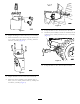
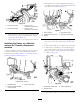
Figure12
1.45-degreetting(2)2.Straighttting(3)
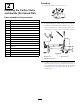
3.Removetheboltssecuringtheleftpaneltothemachine.
4.Usingtheleftpanelbolts,installthevalveassemblyto
themachine(refertoFigure13).
A
g025906
B
Figure13
4
InstallingtheHoses
(ProSneak360)
Partsneededforthisprocedure:
2
Hose,114.3cm(45inches)
1
Hose,91.44cm(36inches)
1
Hose,37.44cm(143/4inches)
1Hoseconnector
InstallingtheHosesonMachineswith
orwithouttheTrencherAttachment
Installed
1
2
3
4
1
3
g021979
2
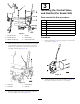
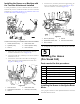
Figure14
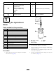
ControlValveViews
1.45-degreetting(PortB)
(45-inchhosefromthe
Motor)
3.45-degreetting(PortA)
(45-inchhosefromMotor)
2.90-degreetting(Outport)
(HoseB143/4-inchhose
tothePlowValve)
4.Straighttting(InPort)
(HoseC/36-inchhose)
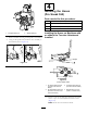
1.Routea114.3cm(45inch)hosefromportAonthe
motortoportAonthehydra-borer-controlvalve
(Figure15).
Note:Routethehosesundertheframe.
8