
Installation Instructions

1
All Rights Reserved
Printed in the USA
2002 by The Toro Company
8111 Lyndale Avenue South
Bloomington, MN 55420-1196
Reel Shutoff Kit
Greensmaster
3
Part No. 28-2150
Form No. 3310-958 Rev B
Installation Instructions
Important Thoroughly clean the valve bank area
before disassembling any components.
Note: Removing the seat and right side panel will ease
installation.
1. Raise the front wheels 3 to 6 inches to slow the oil
drainage from the valve, and place a drain pan beneath
the valve section.
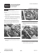
2. Remove the lift check plugs from the #1 and #2 spool
section, oil the o-rings, and insert a check plug into each
spool hole (Fig. 1). Push the plugs to the bottom of the
hole with a clean screwdriver or drift punch.
Note: On Greensmaster 3 models 04340 and 04345,
disconnect the wire connector from the #2 valve section
switch, or the #1 valve section switch (on later traction
units), remove and rotate the switch bonnet 180°, and
reinstall the bonnet and wire.
Figure 1
3. Install a rubber hose and hose clamps to each shutoff
valve, oil the o-rings, and install them into each spool
hole (Fig. 2).
Figure 2
4. Install the front bracket and knob assemblies (Fig. 3).
Tighten the hose clamps and rotate the knobs to ensure
that the hose clamps do not interfere with other parts of
the machine.
Figure 3
5. Lower the machine, install any parts that were removed,
and check the fluid level. Test run the machine to check
operation and test for possible leakage.