
Service Manual
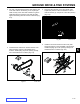

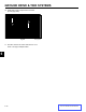
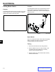


Table Of Contents
- 1 Safety - 30in Aer 4 web.pdf
- 2 Specs n Maint - 30in Aer 4 web.pdf
- Torque Specifications
- Standard Torque for Dry, Zinc Plated & Steel Fasteners (Inch Series)
- Standard Torque for Dry, Zinc & Steel Fasteners (Metric Fasteners)
- 30” Aerator Specifications
- Recommended Maintenance Schedule
- Premaintenance Procedures
- Engine Maintenance
- Fuel System Maintenance
- Electrical System Maintenance
- Drive System Maintenance
- Check Tire Pressures
- Check Wheel Hub Nuts Torque Specification
- Check Wheel Lug Nuts Torque Specification
- Check Condition Of Chains
- Check Condition Of Sprockets
- Check Transmission Output Shaft Nut Torque Specification
- Jackshaft Drive Chain Tension Adjustment
- Drive Wheel Chain Tension Adjustment
- Caster Pivot Bearings Pre-Load Adjustment
- Brake Maintenance
- Belt Maintenance
- Controls System Maintenance
- Hydraulic System Maintenance
- Tine Maintenance
- 3 Chassis - 30in Aer 4 web.pdf
- 4 Hydraulics n Engine Mountg - 30in Aer 4 web.pdf
- Hydraulics
- Checking the Transmission Expansion Tank Hydraulic Oil
- Servicing the Auxiliary Hydraulic Oil
- Changing Auxiliary Hydraulic Reservoir Fluid and Filter
- Changing Hydraulic Transmission Filters and Fluid
- Transmission Belt Replacement
- Transmission Replacement
- Hydraulic Pump Belt Removal & Installation
- Idler Arm Removal & Installation
- Hydraulic Pump Rebuild
- Hydraulic Pump Assembly
- Hydraulic Cylinder Rebuild
- Engine
- Engine Replacement
- 5 Ground Dr n Tine Systems- 30in Aer 4 web.pdf
- 6 - Electrical - 30in Aer 4 web.pdf
ELECTRICAL
6-4
Toro 30” Aerator Service Manual
6
How It Works
This is a “normally open (NO)” switch. When the parking
brake is engaged, the switch is closed and there is
continuity between the switch terminals.
Testing
1. Disconnect the switch from the wiring harness.
2. With a multimeter set to the “Ohms” setting or use
a continuity light. Verify that there is continuity
between the terminals (plunger in).
3. With the plunger out, there should be NO continuity
between the terminals.
Fig. 229 IMG-0001a
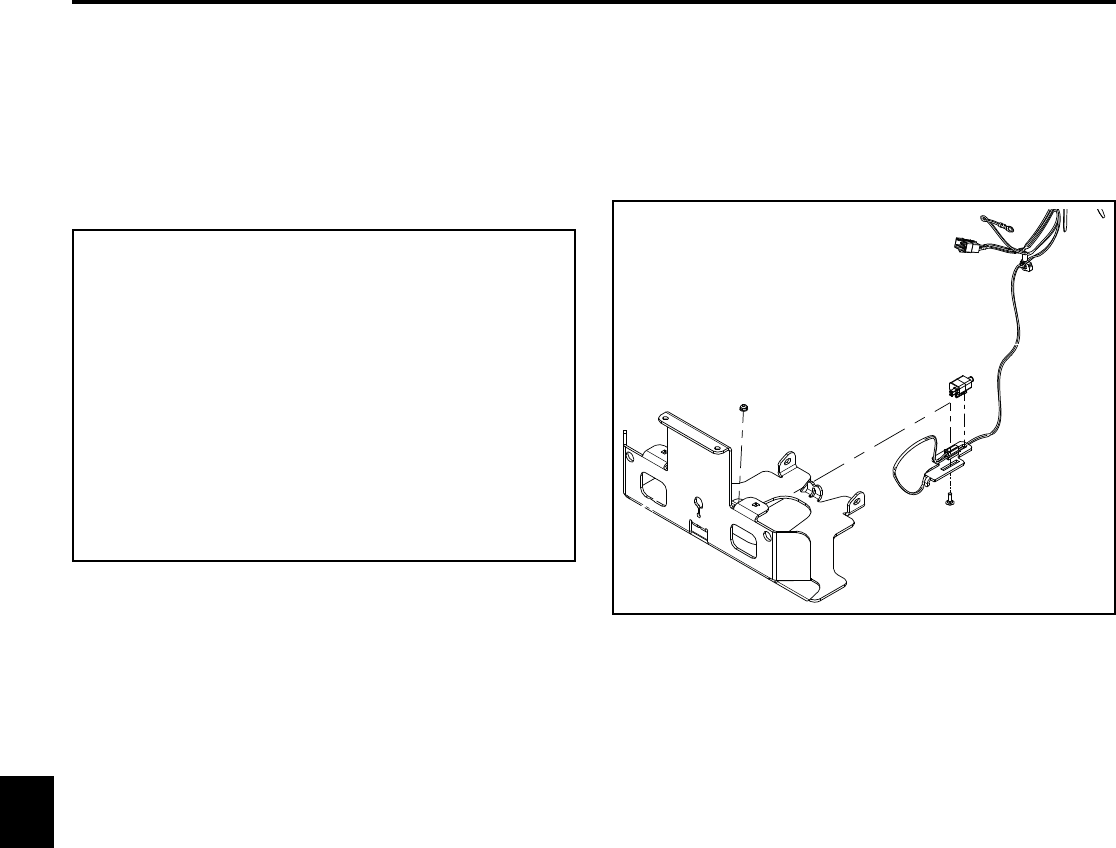
Location
The parking brake switch (A) is located between the two
hydro pumps mounted to the transmission guard. It is
connected to a slide bracket, which is used to adjust the
switch (Fig. 230).
Fig. 230 neutral switch
Parking Brake Switch
Purpose
The parking brake switch is part of the safety circuit. The
switch is used to ensure the parking brake is engaged
allowing the machine to start (Fig. 229).
A