
Service Manual

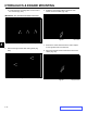

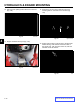
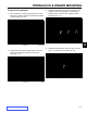


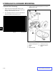
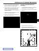
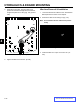
Table Of Contents
- 1 Safety - 30in Aer 4 web.pdf
- 2 Specs n Maint - 30in Aer 4 web.pdf
- Torque Specifications
- Standard Torque for Dry, Zinc Plated & Steel Fasteners (Inch Series)
- Standard Torque for Dry, Zinc & Steel Fasteners (Metric Fasteners)
- 30” Aerator Specifications
- Recommended Maintenance Schedule
- Premaintenance Procedures
- Engine Maintenance
- Fuel System Maintenance
- Electrical System Maintenance
- Drive System Maintenance
- Check Tire Pressures
- Check Wheel Hub Nuts Torque Specification
- Check Wheel Lug Nuts Torque Specification
- Check Condition Of Chains
- Check Condition Of Sprockets
- Check Transmission Output Shaft Nut Torque Specification
- Jackshaft Drive Chain Tension Adjustment
- Drive Wheel Chain Tension Adjustment
- Caster Pivot Bearings Pre-Load Adjustment
- Brake Maintenance
- Belt Maintenance
- Controls System Maintenance
- Hydraulic System Maintenance
- Tine Maintenance
- 3 Chassis - 30in Aer 4 web.pdf
- 4 Hydraulics n Engine Mountg - 30in Aer 4 web.pdf
- Hydraulics
- Checking the Transmission Expansion Tank Hydraulic Oil
- Servicing the Auxiliary Hydraulic Oil
- Changing Auxiliary Hydraulic Reservoir Fluid and Filter
- Changing Hydraulic Transmission Filters and Fluid
- Transmission Belt Replacement
- Transmission Replacement
- Hydraulic Pump Belt Removal & Installation
- Idler Arm Removal & Installation
- Hydraulic Pump Rebuild
- Hydraulic Pump Assembly
- Hydraulic Cylinder Rebuild
- Engine
- Engine Replacement
- 5 Ground Dr n Tine Systems- 30in Aer 4 web.pdf
- 6 - Electrical - 30in Aer 4 web.pdf
HYDRAULICS & ENGINE MOUNTING
4-18
Toro 30” Aerator Service Manual
4
A. 2-3/8”
8. Insert the ball of the park brake cable thriough the
park brake yoke and install yoke as shown between
the two transaxles (Fig. 116).
Fig. 116 yoke
5. Install the pivot arm tensioner (Fig. 113). Torque
bolts to 20 ft-lbs. (27 Nm). Tighten the compres sion
spring until the spring measures 2-3/8” with a new
belt. After run-in, recheck the spring and it should not
be more than 2-5/8”.
Fig. 113 tensioner
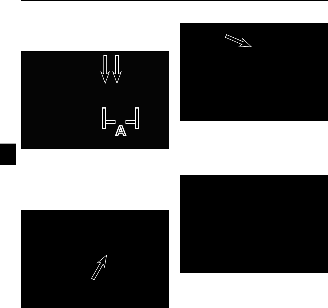
7. Install the park brake cable (Fig. 115).
Fig. 115 park brake
A
6. Reconnect the bell crank control links to the bell
cranks (Fig. 114).
Fig. 114 linkage removal