
Service Manual

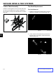

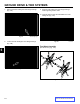
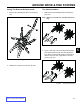


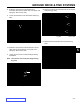
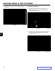
Table Of Contents
- 1 Safety - 30in Aer 4 web.pdf
- 2 Specs n Maint - 30in Aer 4 web.pdf
- Torque Specifications
- Standard Torque for Dry, Zinc Plated & Steel Fasteners (Inch Series)
- Standard Torque for Dry, Zinc & Steel Fasteners (Metric Fasteners)
- 30” Aerator Specifications
- Recommended Maintenance Schedule
- Premaintenance Procedures
- Engine Maintenance
- Fuel System Maintenance
- Electrical System Maintenance
- Drive System Maintenance
- Check Tire Pressures
- Check Wheel Hub Nuts Torque Specification
- Check Wheel Lug Nuts Torque Specification
- Check Condition Of Chains
- Check Condition Of Sprockets
- Check Transmission Output Shaft Nut Torque Specification
- Jackshaft Drive Chain Tension Adjustment
- Drive Wheel Chain Tension Adjustment
- Caster Pivot Bearings Pre-Load Adjustment
- Brake Maintenance
- Belt Maintenance
- Controls System Maintenance
- Hydraulic System Maintenance
- Tine Maintenance
- 3 Chassis - 30in Aer 4 web.pdf
- 4 Hydraulics n Engine Mountg - 30in Aer 4 web.pdf
- Hydraulics
- Checking the Transmission Expansion Tank Hydraulic Oil
- Servicing the Auxiliary Hydraulic Oil
- Changing Auxiliary Hydraulic Reservoir Fluid and Filter
- Changing Hydraulic Transmission Filters and Fluid
- Transmission Belt Replacement
- Transmission Replacement
- Hydraulic Pump Belt Removal & Installation
- Idler Arm Removal & Installation
- Hydraulic Pump Rebuild
- Hydraulic Pump Assembly
- Hydraulic Cylinder Rebuild
- Engine
- Engine Replacement
- 5 Ground Dr n Tine Systems- 30in Aer 4 web.pdf
- 6 - Electrical - 30in Aer 4 web.pdf
GROUND DRIVE & TINE SYSTEMS
5-4
Toro 30” Aerator Service Manual
5
Tine Shaft Replacement
Tine Shaft Removal
1. Rotate the wheels until the master links on the drive
chains are in a position to be removed (Fig. 181).
Fig. 180 tine chain connector link
Fig. 181 drive chains
Tinebar Chain Assembly
Install the connecting links so the cover plate and spring
clip are to the OUTSIDE of the machine. Install spring
clip so opening is away from forward direction of rotation
(Fig. 180).
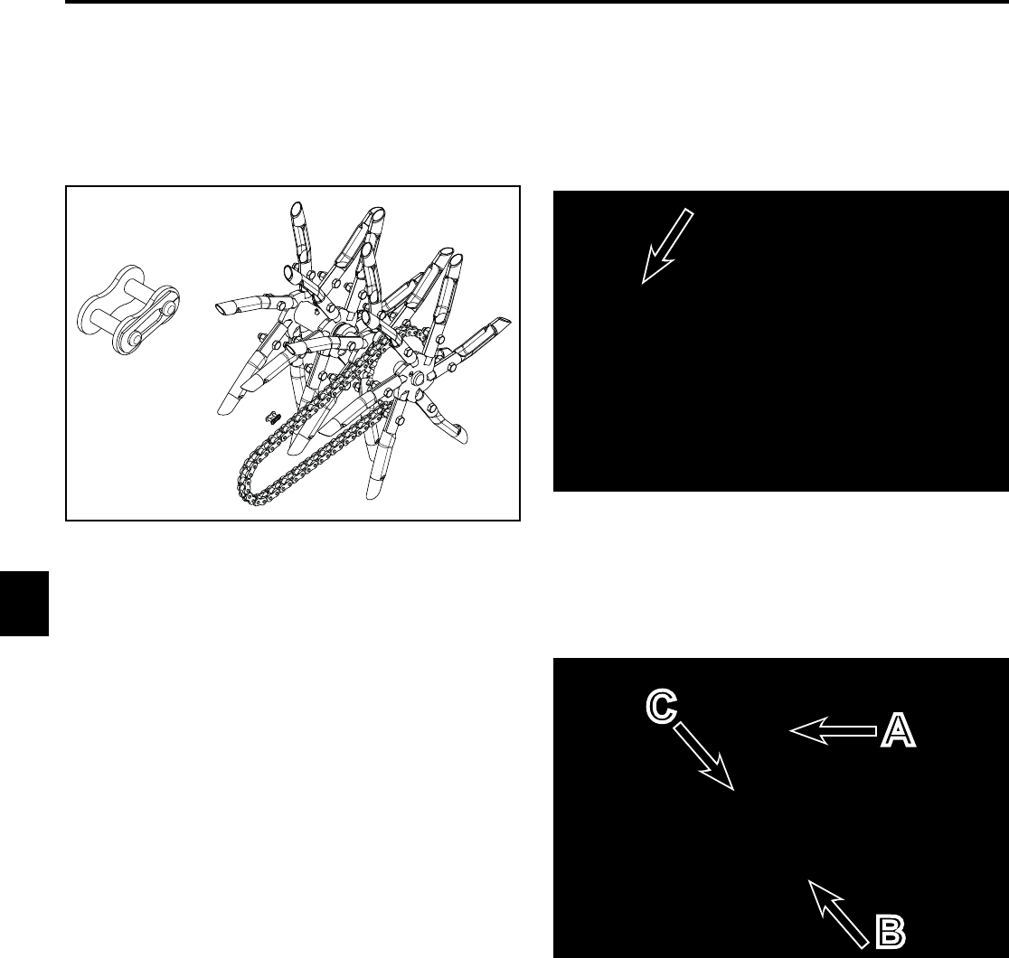
2. Loosen the drive wheel tensioners (A) and remove
the spring clips, cover plates, master links (B) and
chains (C) (Fig. 182).
Fig. 182 drive tensioner
B
C
A