Form No. 3327-516 1800 Power Curve Snowthrower Model No.
Contents Page Introduction . . . . . . . . . . . . . . . . . . . . . . . . . . . . . . . . 2 Important Safety Instructions . . . . . . . . . . . . . . . . . . 3 Safety and Instruction Decals . . . . . . . . . . . . . . . 4 Assembly . . . . . . . . . . . . . . . . . . . . . . . . . . . . . . . . . . 4 Installing the Upper Handle and Chute Crank . . 4 Installing the Discharge Chute . . . . . . . . . . . . . . . 5 Before Starting . . . . . . . . . . . . . . . . . . . . . . . . . . . . . .
IMPORTANT SAFETY INSTRUCTIONS Don’t abuse cord—Never carry snowthrower by cord or yank it to disconnect from receptacle. Keep cord from heat, oil, and sharp edges. (Does not apply to battery-operated snowthrowers.) Keep hands away from moving parts. When using an electrical appliance, basic precautions should always be followed, including the following: Keep guards in place and in working order.
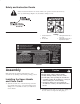
Safety and Instruction Decals Safety decals and instructions are easily visible to the operator and are located near any area of potential danger. Replace any decal that is damaged or lost. On Handle 73-0460 1. Read the Operator’s Manual. 2. Electrocution 3. Cutting/dismemberment of foot, auger 4. Cutting/dismemberment of fingers/hand, impeller 104-9382 Assembly Caution Note: Determine the left and right hand sides of the snowthrower by standing in the normal operating position.
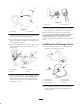
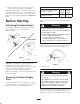
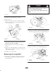
1 SQUEEZE 2 1 1533 Figure 4 2 1. Chute crank 2. Chute crank gear 1531 7. Secure the upper and lower tubing and the mounting plate together with 2 machine screws and locknuts. Figure 2 1. Upper tubing 2. Lower tubing Note: Position the screw heads on the outside of the mounting plate. Be careful not to damage the internal electrical wiring when you insert the screws. If the wiring blocks the hole, use a blunt 1/8-in. punch to carefully route the electrical wiring away from the aligned holes. 3.
3. Secure the deflector to the discharge chute with 2 carriage bolts, metal washers, and locknuts. Extension Cord Chart If length of extension cord is less than or equal to: Note: Ensure that the square shoulders on the carriage bolts align with the inside square on the discharge chute. Position the metal washers to the outside of the chute deflector as shown in Figure 5. Do not overtighten the bolts. Assure wire size gauge (A.W.G.) in cord is: 100 ft. (30 m) 150 ft.
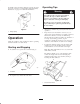
Operating Tips the handle socket, insert the enlarged prong into the wide slot in the extension cord end. Refer to Important Safety Instructions on page 3 for additional information. Warning 1 If snowthrower hits a foreign object while in operation, the object could be thrown in operator’s or bystander’s direction. Thrown objects could cause serious personal injury. Keep the area to be cleared free of all foreign objects which may be picked up and thrown by the rotor blades.
Warning Warning A gap between the discharge chute and the chute deflector may allow snow and anything that can be picked up by snowthrower to fly in the direction of the operator. Thrown objects could cause serious personal injury. When using the secondary handle, never direct the snow discharge chute at the operator or at bystanders. The snowthrower can throw foreign objects and cause serious personal injury.
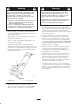
Replacing the Rotor Maintenance 1. Remove the 3 screws that secure the right side cover and the skid to the snowthrower frame (Fig. 13). Note: Determine the left and right sides of the snowthrower by standing in the normal operating position. Warning If the extension cord is plugged into the snowthrower and the key is in the handle, someone could accidentally operate snowthrower while you are performing maintenance on it, causing serious personal injury.
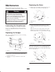
Caution The idler spring could fly in your face while you remove it, causing personal injury. 1 Wear safety goggles when working with the idler spring. 1525 Figure 16 2. Remove the idler spring from the idler arm (Fig. 18). 1. Hex nut 1 2 3. Hold the rotor and pull out the rotor shaft. 4. Remove the rotor. 5. Align the left side of the new rotor with the coupler. The 3 bosses on the rotor end must align with the slots on the coupler (Fig. 17). 1526 Figure 18 1. Idler spring 1 2. Idler arm 4 3.
Note: The bolt must ride on bearings in the small pulley. 5. Lift up the idler arm and slip the belt under the idler pulley (Fig. 20). 7. Place the new belt on the small pulley. 6. Rotate the rotor with your left hand while sliding the belt onto the large pulley with your right hand (Fig. 21). 8. Slide the belt over the motor shaft pulley (Fig. 22). 9. When tightening the bolt, the bolt head and the washers must be flush against the small pulley. Torque the bolt to 25 to 30 in-lb (2.8 to 3.4 N⋅m).
The Toro Promise A Two-Year Full Warranty for Residential Use for the United States, Canada, and Mexico General Conditions The Toro Company and its affiliate, Toro Warranty Company, pursuant to an agreement between them, jointly warrant this product for two years against defects in material or workmanship when used for normal residential purposes. To receive a replacement or repair, at our option, return the complete unit, postage prepaid, to the seller.