
Service Manual
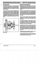
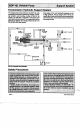


Transmission Hydraulic Support System
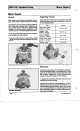
The charge pump incorporated into the
BDP-1
0L
units Since either
of
the main hydraulic passages can be
supplies fluid to keep the closed loop charged, prevent- at high pressure,
two
(2)
charge check valves are
ing cavitation and providing cooling oil flow for the
used
to
direct make-up fluid into the low pressure side
system. An inlet filter
is
required to insure that
only
of
the closed
loop.
These check valves are located in
clean fluid enters the system. The charge relief valve
is
the pump end
cap.
designed
to
maintain the charge pressure at
25
to
70
PSI
at
3600
RPM
input speed.
FILTER