
Installation Instructions
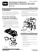
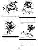
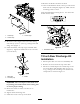
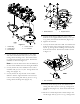
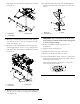


Figure11
1.Outsideap4.Centerchamber
2.Outsidestrap
5.L.H.chamber
3.RHchamber
4.Looselymountthedeckchamberstotheunder
sideofthemowerdeckwith(13)5/16x3/4in.
carriageboltsandangenuts.Theboltheadsare
topositionedinsidethemowerdeck.Positionthe
chambersasshowninFigure11.
Note:Use4boltsandnutsfortheleftchamber,4
forthecenterchamberand5fortherightchamber.
5.Looselymounttheouterchamberstothecenter
chamberwith(2)5/16x3/4in.carriageboltsand
angenuts(Figure11).
6.Looselymountthetopandsideoftherubber
deectorandthesupportbrackettotheleftrear
cornerofthecuttingunitwith(4)5/16x1in.lg.
carriageboltsandangenuts(Figure12).
Figure12
1.Rubberdeector2.Supportbracket
7.Looselymountthetopandsideoftherubber
deectortothesupportbracketwith(3)1/4x3/4
in.lg.bolts,atwashersandlocknuts(Figure12).
8.Tightenthefasteners.
9.LooselymountthesideoftheR.H.footshieldtothe
rightrearcornerofthecuttingunitwith(2)5/16x
3/4in.lg.carriageboltsandangenuts.Insertthe
boltsfromtheinside.Positiontheshieldasshown
inFigure13.
Figure13
1.R.H.footshield
10.Looselymountthetopofthefootshieldtothe
cuttingunitwitha5/16x3/4in.lg.carriagebolt
andangenut(Figure13).Inserttheboltfromthe
inside.
11.Mountanoutsideapandtheoutsidestraptothe
outsideanglewith(2)5/16x1in.lg.carriagebolts
4