
Installation Instructions
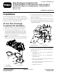
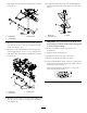


andangenuts.Positionthecomponentsasshown
inFigure14.
Figure14
1.Outsideap3.Outsideangle
2.Outsidestrap
12.Mounttheoutsideangletotherearofthecutting
unitwith(2)5/16x3/4in.lg.carriageboltsand
angenuts(Figure14).
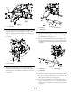
13.Mountthecenterapandthecenterstraptothe
centeranglewith(3)5/16x1in.lg.carriagebolts
andangenuts.Positionthecomponentsasshown
inFigure15.
Figure15
1.Centerap3.Centerangle
2.Centerstrap
14.Mountthecenterangletotherearofthecuttingunit
with(2)5/16x3/4in.lg.carriageboltsandange
nuts(Figure15).
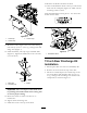
15.Installtheblades,anti-scalpcups,andbladebolts.
Tightenthebladeboltsto85–110ft.-lb.(115–149
N⋅m).
Figure16
1.Bladebolt3.Blade
2.Anti-scalpcup
Important:Thecurvedpartoftheblademust
bepointingtowardtheinsideofthecuttingunit
toensurepropercutting.
16.Rotatethebladestomakesurethereisno
interference.
17.Tightenallthemountingnuts.
18.Installthecoverstothetopofthedeck.
19.Removetheblocksandlowerthedeck.
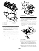
20.Afxanidenticationdecaltothetopofthemower
deckneartheserialplate(Figure18).Makesurethe
mountingsurfaceisclean.
Afxthisidenticationdecal,partno.115–4517
onto72inchmowerdecks
Figure17
5