
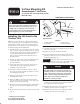
Installation Instructions


1
All Rights Reserved
Printed in the USA
W 2005 by The Toro Company
8111 Lyndale Avenue South
Bloomington, MN 55420-1196
V–Plow Mounting Kit
Groundsmaster
)
200 Series
(To be used with V–Plow Model No. 30750)
Model No. 30311
Form No. 3353–421 Rev. A
Installation Instructions
Danger
Do not start the engine and engage the PTO lever
when PTO shaft is not connected to gear box on
cutting unit or completely removed from the
traction unit because the PTO shaft will rotate
with enough force to cause serious injury.
Installing the Lift Arms to the
Traction Unit
Note: The traction unit must be equipped with a larger
carrier bracket pin, part no. 98–2328. If the traction unit
serial number is 70001 or prior and is equipped with an
old style bracket, a new bracket, part no. 92–9786, must
be obtained from your Toro Distributor.
1. Park the machine on a level surface, lower the cutting
unit to the floor, engage the parking brake, be sure the
traction pedal is in the neutral position, the PTO lever
is in the OFF position, shut the engine OFF and
remove the key from the switch. Move lift lever to
FLOAT position.
2. Remove the cutting unit or other attachment from the
traction unit. Refer to cutting unit or attachment
operator’s manual.
3. On the right side of the traction unit, loosen (do not
remove) the wheel nuts securing wheel and tire
assembly to front wheel studs.
4. Jack up the machine until the front wheel is off the
floor. Use jack stands or block the machine to prevent
it from falling accidentally.
5. Remove the wheel nuts and slide the wheel and tire
assembly off the studs.
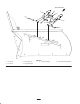
6. Mount the R.H. lift arm to the pivot bracket with a
large pivot pin and cotter pin (Fig. 1 & 2). The grease
fitting to be positioned downward.
7. Mount the rear of the lift arm to the lift cylinder with a
pivot pin and (2) cotter pins (supplied with traction
unit).
8. Hook the brake return spring to the hole in the lift arm
(Fig. 1).
Right Side Shown
1
2
4
3
Figure 1
1. Pivot pin & cotter pin
2. Pivot bracket
3. Lift arm (R.H.)
4. Brake return spring
9. Install the wheel and tire assembly. Torque the wheel
nuts to 45–55 ft–lbs.
10. Repeat the procedure on the left lift arm.
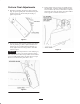
11. Secure the PTO shaft to the mounting bracket on the
left lift arm with the (2) 5/16 x 2.00 in. capscrews and
locknuts supplied (Fig. 2).
Important If the PTO shaft does not have the bolt on,
clevis end type, disconnect and remove the complete PTO
shaft assembly from the traction unit output shaft.
Danger
If the PTO shaft is not connected to the lift arm
mounting bracket or is not disconnected from the
engine output shaft, serious injury could result if
engine is started and the PTO shaft is allowed to
rotate. Refer to the cutting unit Operator’s
Manual for removal procedure.
12. Connect the lift arms together with (2) cross plates, (4)
capscrews, (8) flatwashers and (4) locknuts. Position
the components as shown in figure 2.
13. Mount the R.H. lift arm to the V–plow with a long
mounting pin and (2) cotter pins (Fig. 2).
14. Mount the L.H. lift arm to the V–plow with a short
mounting pin and (2) cotter pins (Fig. 2).