
Installation Instructions

FormNo.3373-182RevA
MechanicalSeatSuspensionKit
Groundsmaster
®
TractionUnits
ModelNo.30312
InstallationInstructions
Installation
Groundsmaster3320and3280tractionunits
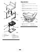
1.Securethelowerseatbracketstotheseatsuspension
withthe(4)boltsincludedwiththekit(Figure1).
2.Removethe(4)boltsandnutssecuringtheseat
mountingplatetothetractionunitframe(
Figure1).
Donotremovetheseatplate.
Note:Toaccomplishthefollowingstep,eachside
oftheseatmountingplatemustbeproppedup,
onesideatatime,tomountthecomponentsand
retainingtheseatswitchwireharnessconnector,in
position,ontopoftheplate.
3.Securethelowerseatbracketsandtheseat
suspensiontotheseatplatewiththe(4)boltsand
nutsincludedwiththekit(
Figure1).
Note:Whenassemblingtheseatcomponents,use
thebackmountingholes.
4.SecuretheL.H.andR.H.seatmountstotheseat
with(4)bolts(
Figure1).Theseatmountsareto
bepositionedsothehighendsaretothefrontof
theseat.
5.Looselyinstalltheseatadjusterstotheseatmounts
withthe(4)bolts,atwashersandnutsincludedwith
thekit(
Figure1).Donottighten.Theseatadjuster
withtheadjustmentleveristobemountedtothe
leftseatmount.
6.Plugtheseatswitchharnessintotheseatswitch
connector.
7.Mounttheupperseatadjusterstotheseatsuspension
withthe(4)nutsincludedwiththekit(
Figure1).
Insertthevinylcapsontotheseatstuds.Tightenthe
fastenerssecuringtheseatadjusters.
Note:Whenassemblingtheseatcomponents,use
thefrontmountingholes.
8.Lowerandsecuretheseatplatew/seatassemblyto
thetractionunitframewiththe(4)boltsandnuts
previouslyremoved.
9.Plugthewireharnessintotheseatswitchharness.
10.Slidetheseatcompletelyforwardandbackwardto
ensureproperoperationandthattheseatswitch
wiresandconnectorsarenotpinchedordono
contactanymovingparts.
Groundsmaster4500and4700tractionunits
1.Unlatchandraisetheseatbase.
2.Securethelowerseatbracketstotheseatsuspension
withthe(4)boltsincludedwiththekit(
Figure1).
3.Securethelowerseatbracketsandtheseat
suspensiontotheseatplatewiththe(4)boltsand
nutsincludedwiththekit(
Figure1).Usetherearset
ofmountingholesintheseatplateandtheforward
setofmountingholesinthelowerseatbrackets.
4.Mounttheupperseatbracketstotheseatwiththe
(4)bolts,atwashersandnutsincludedwiththekit
(
Figure1).Usethefrontsetofmountingholesin
theseat.Theseatbracketwiththeadjustmentlever
istobemountedtotheleftsideoftheseat.
5.Mounttheupperseatbracketstotheseatsuspension
withthe(4)washersandnutsincludedwiththekit
(
Figure1).Usetherearsetofmountingholesinthe
seatsuspension.Thewashersaretobepositioned
betweentheseatbracketsandtheseatsuspension.
Insertthevinylcapsontotheseatstuds.
6.Lowerandlatchtheseatbasew/seatassembly.
7.Plugtheseatswitchconnectorintothewireharness
connector.
8.Slidetheseatcompletelyforwardandbackwardto
ensureproperoperationandthattheseatswitch
wiresandconnectorsarenotpinchedordono
contactanymovingparts.
©2012—TheToro®Company
8111LyndaleAvenueSouth
Bloomington,MN55420
Registeratwww.Toro.com.
OriginalInstructions(EN)
PrintedintheUSA.
AllRightsReserved