
Installation Instructions

10
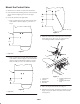
Connect the Wire Harness
1. Unplug the wire harness connector from the seat switch.
2. Plug the tee end of the hopper switch harness into the
seat switch and the seat switch harness.
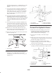
3. Route the harness to the hopper switch mounted to the
frame tube (Fig. 16). Plug the harness into the switch.
1
Figure 16
1. Hopper switch
4. Secure the harness to stationary frame components with
cable ties.
Mount Hopper Assembly
1. Remove the tie straps securing the tie rods to the hopper
arms. Install (2) 5/16 – 18 x 1” lg. carriage bolts and
flange nuts in hopper arm holes where tie straps
previously were.
2. Slide the hopper assembly (hopper cover to rear) into
the side frame while aligning the mounting holes in
hopper with the holes in frame (Fig. 17).
2
2
1
Figure 17
1. Hopper assembly 2. Mounting pins
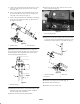
3. Secure the hopper to the frame with (2) welded
mounting pins and hair pin cotters (Fig. 17).
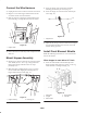
4. Secure the hopper tie rods to the frame with hair pin
cotters (Fig. 18).
1
Figure 18
1. Hopper tie rod
5. Adjust the tie rods up or down to make sure the hopper
is level with the machine and it does not contact the
machine during operation.
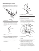
Install Front Blowout Shields
Note: The following instructions are as viewed from the
front of the machine.
When hopper is used with a 52” Deck
1. Secure the wide shield to the left inside lip of the
hopper opening with a long flat, (3) #10 – 24 X 1” lg.
screws and #10 – 24 flange nuts (Fig. 19).
1
2
4
5
2
3
Figure 19
1. Wide shield
2. Long flat
3. Narrow shield
4. Narrow shield
5. Short flat