
Installation Instructions


11
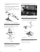
2. Secure the narrow shield to the right inside lip of the
hopper opening with a long flat, (3) #10 – 24 X 1” lg.
screws and #10 – 24 flange nuts (Fig. 19).
3. Secure the top shield to the upper inside lip of the
hopper opening with a short flat, (2) #10 – 24 X 1” lg.
screws and #10 – 24 flange nuts (Fig. 19). Use the (2)
mounting holes on the right side of the opening only.
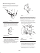
When hopper is used with a 60” Deck
1. Secure the wide shield to the right inside lip of the
hopper opening with a long flat, (3) #10 – 24 X 1” lg.
screws and #10 – 24 flange nuts (Fig. 20).
2. Secure the narrow shield to the left inside lip of the
hopper opening with a long flat, (3) #10 – 24 X 1” lg.
screws and #10 – 24 flange nuts (Fig. 20).
3. Cut 1–1/2” of material off the bottom edge of the top
shield. Secure the top shield to the upper inside lip of
hopper opening with a short flat, (2) #10 – 24 X 1”. lg.
screws and #10–24 flange nuts (Fig. 20). Use the (2)
mounting holes on the left side of the opening only.
1
2
4
5
2
6
3
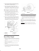
Figure 20
1. Wide shield
2. Long flat
3. Narrow shield
4. Narrow shield
5. Short flat
6. Cut off 1–1/2”
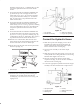
Mount Wheel Weight
1. Measure the depth of the wheel rim. This is achieved by
measuring the distance from the hole to the outside edge
of the rim.
2. Add 3–7/8” to the measurement attained. This becomes
dimension ”A” in figure 21.
3. Thread a hex nut onto each threaded rod to the ”A”
dimension.
4. Insert the threaded rods through two opposite holes in
the rim and secure them in place with 1/2” lockwashers
and hex nuts (Fig. 21).
1
2
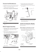
Figure 21
1. Wheel weight 2. Threaded rod
5. Place the wheel weight over the ends of the threaded
rods and secure in place with flatwashers, lockwashers
and hex nuts (Fig. 21). Do not overtighten the hex nuts
or damage to the plastic housing of the weight may
occur.
Note: If there is excess thread protruding from the nuts or
inside of wheel, cut it off with a hacksaw. The threaded rod
must not contact any parts of the machine when the wheel
is rotating.
Important Refer to the weight chart in the Traction
Unit Operator’s Manual for additional weight requirements.