
Installation Instructions

4
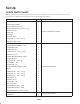
Set Up
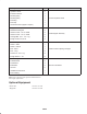
LOOSE PARTS CHART
Note: Use this chart as a checklist to assure all parts necessary for assembly have been received. Without these parts, total
set-up cannot be completed. Some parts may have already been assembled at factory.
Description
Qty. Use
Control Valve Assembly
Control Valve Handle
Control Valve Pivot Lever
Socket Head Screw 10–24 x 1–1/4” lg.
Locknut #10–24
Clevis Pin
Cotter Pin
Hydraulic Hose
Capscrew 1/4 – 20 x 2–3/4” lg.
Flange Locknut 1/4–20
1
1
1
1
1
1
1
1
3
3
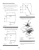
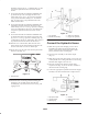
Mount Control Valve to Fender
Frame Assembly
Hopper Mounting Bracket – Left
Capscrew #10–24
Locknut #10–24
Capscrew 5/16 – 18 x 1–1/4” lg.
Locknut 5/16–18
Hopper Mounting Bracket – Right
Coupler Bracket
Capscrew 3/8 – 16 x 1” lg.
Lockwasher – 3/8
Locknut 3/8 – 16
Hopper Mounting Bracket – Rear
Strap
Capscrew 1/2 – 13 x 1–1/4” lg.
Capscrew 1/2 – 13 x 1–1/2” lg.
Capscrew 1/2 – 13 x 3–1/2” lg.
Flatwasher 1/2
Locknut 1/2–13
Lockwasher–1/2
Disconnect Pin
Welded Mounting Pin – Long
Welded Mounting Pin – Short
Self Tapping Screw 1/4–20– x 3/4” lg.
1
1
4
4
4
4
1
1
4
2
2
1
2
2
2
2
4
4
2
1
1
1
2
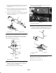
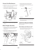
Install Frame Assembly
Wire Harness
Cable Ties
1
6
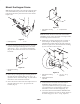
Connect Wire Harness