
Installation Instructions

7
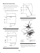
7. Connect the steering hose (from the lift valve “P” port)
to the 90_ fitting on the operator side of the control
valve (Fig. 4).
8. Connect the hydraulic hose (included in the kit) to the
“P” port of the lift valve and to the 90_ fitting on the
outer side of the control valve (Fig. 4).
9. Connect the (2) hydraulic hose assemblies to the fittings
on the top of the control valve (Fig. 5). Make sure the
O–rings are in position.
1
1
2
Figure 5
1. Hydraulic hoses 2. Protective sleeve
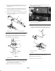
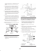
Note: Make sure the (2) hydraulic hoses are oriented so
they point straight out the left side of the control valve, as
shown in figure 6. This will eliminate the chance of the
hoses interfering with the fuel tank.
1
1
Figure 6
1. Hydraulic hose (2)
10. Install the protective sleeve over the hoses (Fig. 5). The
remainder of the hose installation will be completed
after the hopper frame is installed.
11. Remove the drain pan from under machine.
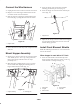
12. Remove the knock–out plug, under the decal, in the
lower control panel (Fig. 7).
1
Figure 7
1. Knock–out plug location
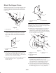
13. Mount the control valve handle to the valve spool with
a clevis pin and cotter pin. Mount the pivot lever to the
handle with a socket head screw and lock nut (Fig. 8).
2
1
3
4
Figure 8
1. Control valve handle
2. Pivot lever
3. Valve spool
4.
14. Install the control knob to the handle (Fig. 8).
15. Install the fuel tank fasteners.
16. Install the seat base and the seat.