
Installation Instructions

8
Mount the Hopper Frame
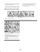
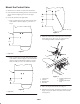
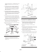
Note: Remove the hairpin cotter and pin securing the right
side of the ROPS to the pivot bracket. Re–install the pin
from the left side of the pivot bracket and secure with the
hairpin cotter.
2
1
Figure 9
1. ROPS (right side) 2. Pin
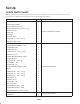
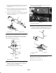
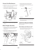
1. Using the mounting holes in the left side of the frame,
secure the left hopper mounting bracket to the frame
with (4) 5/16 – 18 x 1–1/4” capscrews and locknuts
(Fig. 10). The notch in the bracket is to fit around the
hood latch.
1
Figure 10
1. Left hopper mounting
bracket
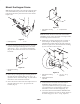
2. Secure the top of the right hopper mounting bracket to
the right side of the machine with (2) 3/8–16 x 1” lg.
capscrews and 3/8” lockwashers (Fig. 11). The notch in
the bracket is to fit around the hood latch.
3. Secure the bottom of the bracket and coupler bracket to
the frame with (2) 3/8–16 x 1” lg. capscrews and
locknuts (Fig. 11).
1
2
Figure 11
1. Right hopper mounting
bracket
2. Coupler bracket
Note: On models 30343 and 30344 with serial numbers
260000001 and up, remove the outside rear weight. Retain
the mounting fasteners for future use.
4. Position the rear hopper bracket on the rear frame, as
shown in figure 12, while aligning the (2) bottom
mounting holes with the holes in the frame. Using the
bracket as a guide, locate, mark and drill the remaining
(2) 9/16” dia. holes in the rear frame.
1
2
2
3
3
Figure 12
1. Rear hopper mounting
bracket
2. Drill the holes for these
capscrews
3. 1/2–13 x 1–1/4” lg.
capscrews.
5. On models 30343 and 30344 with serial numbers
260000001 and up, install (2) 1/2–13 x 1–1/4”
capscrews (included in kit) and (2) previously removed
1/2” lockwashers and 1/2” flatwashers in the outer
frame holes to secure the inside weight (Fig. 12).
6. On traction units with serial numbers 250000001 thru
259999999, mount the top of the rear hopper bracket to
the frame using (2) 1/2–13 x 1–1/4” lg. capscrews,