
Installation Instructions

9
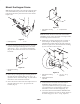
mounting strap and (2) 1/2 – 13 locknuts (Fig. 12). The
strap is to be positioned between the frame and the
bracket.
7. On traction units with serial numbers 260000001 and
up, mount the top of the rear hopper bracket to the
frame using (2) 1/2–13 x 3” lg. capscrews, mounting
strap, (2) 1/2” flatwashers and (2) 1/2 – 13 locknuts
(Fig. 12). The strap is to be positioned between the
frame and the bracket.
8. On traction units with serial numbers 250000001 thru
259999999, mount the bottom of the bracket to the
frame with (2) 1/2–13 x 1–1/2” lg. capscrews, mounting
strap, (2) 1/2 flatwashers and (2) 1/2–13 locknuts. The
strap is to be positioned between the frame and the
bracket.
9. On traction units with serial numbers 260000001 and
up, mount the bottom of the bracket to the frame with
(2) 1/2–13 x 1–1/2” lg. capscrews, mounting strap, (2)
1/2 flatwashers and (2) 1/2” lockwashers. The strap is to
be positioned between the frame and the bracket.
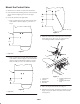
10. From the rear of the machine, slide the front of the
hopper frame onto the side mounting bracket pins and
the rear of the frame over the rear bracket pin.
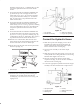
11. Secure the rear of the frame to the bracket pin with the
disconnect pin (Fig. 13).
1
Figure 13
1. Disconnect pin
12. Install the short and the long welded mounting pins
through the arm assembly and the main lift arm
assembly (Fig. 14). Secure with 1/4–20 x 3/4” lg. self
tapping screws.
2
1
3
4
Figure 14
1. Arm assembly
2. Main lift arm assembly
3. Short pin (on left side)
4. Long pin (on right side)
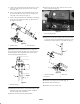
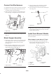
Connect the Hydraulic Hoses
1. Slide the loop end of the dust plug over the end of
hydraulic hose from front valve fitting. Insert the
female coupler thru the bottom hole in the coupler
bracket and secure with a retaining ring.
2. Secure the hose assembly to the female coupler
(Fig. 15).
3. Slide the loop end of the dust cap (Fig. 15) over the end
of the hydraulic hose coming from the rear valve fitting.
Install the male nipple to the hose end.
4. Insert the end of the hose thru the top hole in the
coupler bracket (Fig. 15). Secure the hose assembly to
the bracket with a retaining ring.
5. Connect the appropriate hydraulic hose from the hopper
assembly to the hoses installed to the coupler bracket.
2
1
3
4
6
5
3
Figure 15
1. Top hydraulic hose
2. Coupler bracket
3. Retaining ring
4. Dust cap
5. Bottom hydraulic hose
6. Dust plug