Form No. 3393-577 Rev A Blower Kit 60 in Side Discharge Mowers for Groundsmaster® 3320/3280-D Traction Unit Model No. 30357—Serial No. 315000001 and Up Register at www.Toro.com.
Contents WARNING CALIFORNIA Proposition 65 Warning This product contains a chemical or chemicals known to the State of California to cause cancer, birth defects, or reproductive harm. Safety ........................................................................... 3 Before Operating .................................................... 3 While Operating...................................................... 3 Maintenance ...........................................................
Safety • Before starting the engine: – Engage parking brake. This machine has been designed in accordance with ANSI B71.4-2012. – Make sure traction pedal is in neutral and PTO is in disengage position. Hazard control and accident prevention are dependent upon the awareness, concern, and proper training of the personnel involved in the operation, transport, maintenance, and storage of the machine. Improper use or maintenance of the machine can result in injury or death.
or cardboard, not hands, to search for leaks. Hydraulic fluid escaping under pressure can have sufficient force to penetrate skin and cause serious injury. If fluid is ejected into the skin, it must be surgically removed within a few hours by a doctor familiar with this form of injury or gangrene may result. lead to thrown object injuries. Do not resume mowing until area is cleared. • Never raise the cutting unit while the blades or other parts are rotating.
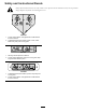
Safety and Instructional Decals Safety decals and instructions are easily visible to the operator and are located near any area of potential danger. Replace any decal that is damaged or lost. 106-6753 1. Thrown object hazard—keep bystanders a safe distance from the machine. 2. Cutting/dismemberment hazard of hand or foot, mower blade—stay away from moving parts. 93–7301 1. Warning-read the Operator's Manual. 2. Thrown object hazard-stay away from moving parts; keep all guards and shields in place.
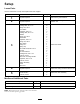
Setup Loose Parts Use the chart below to verify that all parts have been shipped. Procedure Description 1 2 Use Qty.
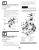
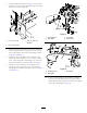
3. Remove the hair pin cotters and clevis pins securing the lift arms to the castor arm brackets (Figure 3). 1 4. Roll the cutting unit away from the traction unit, separating the male and female sections of the PTO shaft. Removing the Grass Deflector DANGER No Parts Required If the engine is started and the PTO shaft is allowed to rotate, serious injury could result. Procedure Do not start the engine and engage the PTO lever when the PTO shaft is not connected to the gear box on the cutting unit.
3 Mounting the Blower Parts needed for this procedure: 1 Discharge shelf 2 Carriage bolt, 3/8 x 1 in 2 Flange nut, 3/8 in 1 Front baffle 3 Capscrew, 3/8 x 1 in 1 Carriage bolt, 3/8 x 1 in 3 Washer 4 Flange nut, 3/8 in 1 Rear baffle 2 Capscrew, 3/8 x 1 in 2 Flange nut, 3/8 in 1 Drive pulley 1 Pulley nut 2 Spring clip 2 Pan head screw, #8 x 1/2 in 2 Nut, #8 1 Tie-down bracket 3 Carriage bolt, 5/16 x 1 in 3 Locknut, 5/16 in 1 Belt cover mounting bracket 2 Capscrew, 5/16
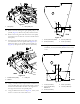
6. Using the dimensions shown in Figure 6, locate, mark and drill a 1.03 cm (.406 inch) diameter hole in the right front corner of the cutting unit. Figure 7 Figure 6 1. 3.2 cm (1.25 inch) 1. Discharge shelf 3. Front baffle 2. Rear baffle 4. Carriage bolt 3. 1.03 cm (.406 inch diameter) 2. 10.1 cm (4.00 inch) 7. Mount the discharge shelf to the front and underside of the cutting unit with 2 carriage bolts (3/8 x 1 inch) and 3/8 inch flange nuts. Position the baffle as shown in Figure 7 andFigure 8.
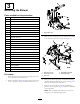
Figure 9 1. Idler pulley 2. Drive pulley nut 11. Remove the nut securing the right spindle pulley to the spindle (Figure 9). Remove the pulley and the washer. 12. Remove the V-ring seal from the bottom of the pulley and install it into the bottom of the new double sheave drive pulley. Figure 11 13. Install the new double sheave drive pulley w/V-ring seal and washer onto the spindle shaft (Figure 10). Secure the pulley to the spindle with the pulley nut (Figure 10).
17. Mount a spring clip (Figure 13) into each of the new holes in the center deck cover with a #8 x 1/2 inch pan head screw and a #8 nut. and 5/16 lock nuts. Position the bracket as shown in Figure 15. The bolt heads are to be positioned inside the cutting unit. Figure 13 1. Spring clip Figure 15 1. Tie-down bracket 18. Install the center deck cover to the cutting unit. 19. Using the dimensions shown in Figure 14, locate, mark and drill a 2.2 cm (0.
25. Install the drive belt onto the lower jack shaft pulley (Figure 16). 26. Adjust the belt tension as follows: Drive belt • Loosen the bolt and nut securing the jack shaft assembly to the adjustment bracket (Figure 17). • Using a 1/2 inch ratchet, torque wrench or similar tool, rotate the jack shaft assembly until the desired belt tension is attained. • Tighten the bolt and nut to lock the adjustment.
7. Push down on the rear of the cutting unit and insert the height of cut rods through the lift arm pads. 5 8. Install the height of cut collars onto the height of cut rods and secure with the clevis pins and hair pin cotters (Figure 19). The head of the clevis pin is to be positioned toward the front of the deck. Mount the Chute Assembly 9. Install a 1/2 x 3/4 inch capscrew and a washer to the top of each height of cut rod (Figure 19).
Operation CAUTION When grass collector is removed, never operate without deflector in place. Think Safety First Carefully read all safety instructions and symbols in the safety section. Knowing this information could help you or bystanders avoid injury. For best performance, regulate traction pedal to keep engine rpm high and somewhat constant. A good rule to follow is: decrease ground speed as the load on the cutting blade increases; and increase ground speed as the load on the blade decreases.
Blower Removal 1. Shut the engine off and wait for all moving parts to stop. 2. Release the latches and remove belt cover. 3. Loosen the bolt and nut securing the jack shaft assembly to the adjusting bracket. Remove the drive belt from the lower jack shaft pulley. 4. Release the latches securing the blower to cutting unit and remove the blower and chute. 5. Insert the drive belt into the belt cover spring clips. 6. Reverse the procedure to reinstall blower assembly.
Maintenance General Maintenance • Check blower gearbox impeller for tightness every 50 hours. Torque impeller shaft bolt to 27 to 29 N-m (240 to 260 in.-lbs). • Clean grass clippings from hood, chute, blower and cutting unit after each use. Wash underside of cutting unit daily with hose. An excessive buildup of clippings will impair collection system performance. • Check belt tension and wear every 50 hours. • The blower gear box should need little maintenance. Check for leakage every 50 hours.
Notes: 17
Notes: 18
Notes: 19
Toro General Commercial Product Warranty A Two-Year Limited Warranty Conditions and Products Covered The Toro Company and its affiliate, Toro Warranty Company, pursuant to an agreement between them, jointly warrant your Toro Commercial product (“Product”) to be free from defects in materials or workmanship for two years or 1500 operational hours*, whichever occurs first. This warranty is applicable to all products with the exception of Aerators (refer to separate warranty statements for these products).