
Operator's Manual
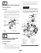
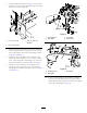

6.UsingthedimensionsshowninFigure6,locate,mark
anddrilla1.03cm(.406inch)diameterholeintheright
frontcornerofthecuttingunit.
Figure6
1.3.2cm(1.25inch)3.1.03cm(.406inch
diameter)
2.10.1cm(4.00inch)
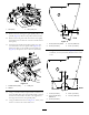
7.Mountthedischargeshelftothefrontandunderside
ofthecuttingunitwith2carriagebolts(3/8x1inch)
and3/8inchangenuts.Positionthebafeasshown
inFigure7andFigure8.
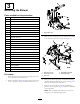
8.Mountthenewfrontbafetotheundersideofthe
cuttingunitwith3capscrews(3/8x1inch),3washers,
3/8x1inchcarriageboltand4angenuts(3/8inch).
PositionthebafeasshowninFigure7andFigure8.
9.Mountthenewrearbafetotheundersideofthe
cuttingunitwith2capscrews(3/8x1inch)and3/8
inchangenuts.PositionthebafeasshowninFigure
7andFigure8.
Figure7
1.Dischargeshelf3.Frontbafe
2.Rearbafe4.Carriagebolt
Figure8
1.Dischargeshelf3.Frontbafe
2.Rearbafe
10.Usinga1/2inchratchet,torquewrenchorsimilar
tool,movetheidlerpulleyawayfromthedrivebeltto
releasethebelttensionandallowthebelttobeslipped
offtherightspindlepulley(Figure9).
9