Form No. 3372-462 Rev A 60in Side Discharge Mower Groundsmaster® 3320/3280-D Traction Unit Model No. 30366—Serial No. 312000001 and Up To register your product or download an Operator's Manual or Parts Catalog at no charge, go to www.Toro.com.
Contents This product complies with all relevant European directives, for details please see the separate product specific Declaration of Conformity (DOC) sheet. Introduction................................................................. 2 Safety ........................................................................... 3 Safe Operating Practices ....................................... 3 Toro Mower Safety ............................................... 4 Safety and Instructional Decals ................
Safety – Use only an approved container. – Never remove fuel cap or add fuel with engine running. Allow engine to cool before refueling. Do not smoke while refueling. This machine meets or exceeds CEN standard EN 836:1997, ISO standard 5395:1990, and ANSI B71.4-2004 specifications in effect at the time of production. – Never refuel or drain the machine indoors. • Check that operator's presence controls, safety switches and shields are attached and functioning properly.
Toro Mower Safety • Do not operate the mower under the influence of alcohol or drugs. • Lightning can cause severe injury or death. If lightning is seen or thunder is heard in the area, do not operate the machine; seek shelter. • Use care when loading or unloading the machine into a trailer or truck. • Use care when approaching blind corners, shrubs, trees, or other objects that may obscure vision.
• Keep your body and hands away from pin hole leaks or nozzles that eject hydraulic fluid under high pressure. Use paper or cardboard, not your hands, to search for leaks. Hydraulic fluid escaping under pressure can have sufficient force to penetrate the skin and cause serious injury. • Before disconnecting or performing any work on the hydraulic system, all pressure in the system must be relieved by stopping the engine and lowering the cutting units to the ground.
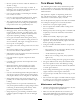
Safety and Instructional Decals Safety decals and instructions are easily visible to the operator and are located near any area of potential danger. Replace any decal that is damaged or lost. 117–4979 1. Entanglement hazard, belt—stay away from moving parts, keep all guards and shields in place. 107-2908 120-6604 1. Thrown object hazard—keep bystanders a safe distance from the machine. 2. Thrown object hazard—do not operate the mower with the deflector up or removed, keep the deflector in place. 1.
100-5622 1. Height of cut adjustment 107-1622 108-1986 1. Height of cut 107-2916 1. Remove the ignition key and read the Operator's Manual before servicing or performing maintenance. 2. Thrown object hazard—do not operate the mower with the deflector up or removed, keep the deflector in place; keep bystanders a safe distance from the machine. 7 3. Cutting/dismemberment hazard of hand or foot, mower blade—stay away from moving parts.
Setup Loose Parts Use the chart below to verify that all parts have been shipped. Procedure Description Use Qty. Pivot pin assembly Cotter pin Lift arm, right Lift arm, left Thrust washer-nylon Clevis pin Hair pin Height of cut collar Clevis pin Hair pin Capscrew, 1/2 x 3/4 inch Washer 2 2 1 1 4 4 2 2 2 2 2 2 3 No parts required – Replace the Traction Unit PTO Shaft (Cutting Unit Model 30366 only) 4 5 No parts required – Connect the PTO shaft to the cutting unit gear box.
1 2 Installing the Lift Arms to the Traction Unit Connecting the Lift Arms to the Cutting Unit Parts needed for this procedure: Parts needed for this procedure: 2 Pivot pin assembly 1 Lift arm, right 2 Cotter pin 1 Lift arm, left 4 Thrust washer-nylon 4 Clevis pin 2 Hair pin 2 Height of cut collar 2 Clevis pin 2 Hair pin 2 Capscrew, 1/2 x 3/4 inch 2 Washer Procedure 1.
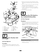
1. Remove the cotter pin, bolts and locknuts securing the female end of the PTO shaft to the traction unit shaft. 2. Remove the PTO shaft from the traction unit shaft and retain it for future applications. 3. Install the female end of the PTO shaft, supplied with the cutting unit, to the traction unit shaft with the cotter pin. 4. Tighten the bolts and locknuts. 4 Connecting the PTO Shaft to the Cutting Unit Gear Box No Parts Required Procedure 1. Slide the male PTO shaft into the female PTO shaft.
Product Overview 5 Specifications Greasing the Machine Note: Specifications and design are subject to change without notice. No Parts Required Width of 60 inches (1.52 m) Cut Procedure Before operating the machine, it must be greased to ensure proper lubricating characteristics; refer to Greasing the Bearings and Bushings. Failure to properly grease the machine will result in premature failure of critical parts.
Adjusting the Height-of-Cut Operation The height-of-cut is adjustable from 1 to 5 inches (25 to 127 mm) in 1/2 inch (13 mm) increments. To adjust the height-of-cut, position the castor wheel axles in the upper or lower holes of the castor forks, add or remove an equal number of spacers from the castor forks and secure the height of cut collar to the desired holes in the height of cut rod. 1. Start the engine and raise the cutting unit off the floor so that the height-of-cut can be changed.
reverse the machines direction to pull any clippings away from the wheel/fork area. 3. Remove the tensioning cap from the spindle shaft (Figure 6) and slide the spindle out of the castor arm. Put the 2 shims (1/8 inch) onto the spindle shaft as they were originally installed. These shims are required to achieve a level across the entire width of the cutting units. Slide the appropriate number of 1/2 inch spacers onto the spindle shaft to get the desired height-of-cut; then slide the washer onto the shaft.
3. Swing the lever back over to tighten the baffle and cam locks (Figure 13). 4. If the cam locks do not lock the baffle into place or it is too tight, loosen the lever and then rotate the cam lock. Adjust the cam lock until the desired locking pressure is achieved. Figure 11 1.
Adjusting the Cutting Unit Pitch Cutting unit pitch is the difference in height-of-cut from the front of the blade plane to the back of the blade plane. Toro recommends a blade pitch of 1/4 in. (6 mm). That is the back of the blade plane is 1/4 in. (6 mm) higher than the front. 1. Position the machine on a level surface on the shop floor. Figure 14 2. Set the cutting unit to the desired height-of-cut. 3. Rotate 1 blade so that it points straight forward. Position B 4.
2. Check and adjust front and rear tractor tire pressure to 20 psi (138 kPa). Operating Tips 3. Check and adjust all castor tire pressures to 50 psi (345 kPa). Mow When Grass is Dry Mow either in the late morning to avoid the dew, which causes grass clumping, or in late afternoon to avoid the damage that can be caused by direct sunlight on the sensitive, freshly mowed grass. 4. Check for bent blades; refer to Checking for a Bent Blade. 5.
Maintenance Recommended Maintenance Schedule(s) Maintenance Service Interval Maintenance Procedure After the first 2 hours • Tighten the castor wheel nuts After the first 10 hours • Tighten the castor wheel nuts • Torque the blade bolts Before each use or daily • Lubricate the castor arm bushings • Lubricate the castor wheel bearings • Check the blades Every 50 hours • • • • • • Check the gear box lubricant Lubricate the grease fittings Tighten the castor wheel nuts Torque the blade bolts Check th
Lubrication Service Interval: Every 50 hours The machine has grease fittings that must be lubricated regularly with No. 2 General Purpose Lithium Base Grease. If the machine is operated under normal conditions, lubricate all bearings and bushings after every 50 hours of operation or immediately after every washing. 1. Lubricate the following areas: Figure 20 • Castor fork shaft bushings (2)(Figure 18) • Lift arm pivots, rear (2) (Figure 21) Figure 21 Figure 18 2.
Figure 23 1. Height-of-cut rod 3. Height-of-cut collar 2. Bolt and washer 4. Hairpin cotter and clevis pin Figure 22 1. Dipstick/fill plug 3. Remove the hairpin and clevis pin securing the height of cut collar to the height of cut rod on the rear of the cutting unit (Figure 23). Remove the height of cut collar. Pre Maintenance 4. Remove the hair pin cotters and clevis pins securing the lift arms to the castor arm brackets (Figure 24).
Figure 25 1. PTO shaft DANGER If the engine is started and the PTO shaft is allowed to rotate, serious injury could result. Do not start the engine and engage the PTO lever when the PTO shaft is not connected to the gear box on the cutting unit. Mounting the Cutting Unit to the Traction Unit 1. Position the machine on a level surface and shut the engine off. 2. Move the cutting unit into position in front of the traction unit. 3. Slide the male PTO shaft into the female PTO shaft (Figure 25). 4.
3. Pull the castor spindle out of the mounting tube. Allow the thrust washer and spacer(s) to remain on the bottom of the spindle. 4. Insert a pin punch into the top or bottom of the mounting tube and drive the bushing out of the tube (Figure 27). Also drive the other bushing out of the tube. Clean the inside of the tubes to remove dirt. Figure 28 Figure 27 1. Castor arm tube 1. Castor wheel 3. Bearing (2) 2. Castor fork 4. Bearing spacer 2. Bushings 5. Slide the bearing spacer into the wheel hub.
Removing and Installing the Blade(s) Inspecting and Sharpening the Blade(s) The blade must be replaced if a solid object is hit, the blade is out-of-balance, worn, or bent. Always use genuine Toro replacement blades to ensure safety and optimum performance. Never use blades made by other manufacturers because they could be dangerous.
Checking and Correcting Mismatch of Blades If there is mismatch between the blades, the grass will appear streaked when it is cut. This problem can be corrected by making sure that the blades are straight and all of the blades are cutting on the same plane. 1. Using a 3 foot (1 meter) long carpenters level, find a level surface on the shop floor. 2. Raise the height-of-cut to the highest position; refer to Adjusting the Height-of-Cut. 3. Lower the cutting unit onto the flat surface.
1. Lower the cutting unit to the shop floor. Remove the belt covers from the top of the cutting unit and set the covers aside. 2. Using a torque wrench or similar tool, move the idler pulley (Figure 33) away from the drive belt to release the belt tension and allow the belt to be slipped off the gearbox pulley (Figure 34). Figure 35 1. Belt routing 5. Install the belt covers. Figure 33 Replacing the Grass Deflector 1.
Figure 36 1. Bolt 5. Spring installed 2. Spacer 6. Grass Deflector 3. Locknut 7. L end of spring, place behind deck edge before installing bolt 4. Spring 8.
Notes: 26
Notes: 27
The Toro Total Coverage Guarantee A Limited Warranty Conditions and Products Covered The Toro Company and its affiliate, Toro Warranty Company, pursuant to an agreement between them, jointly warrant your Toro Commercial product (“Product”) to be free from defects in materials or workmanship for two years or 1500 operational hours*, whichever occurs first. This warranty is applicable to all products with the exception of Aerators (refer to separate warranty statements for these products).