Form No. 3356–632 Rev B 72 in Side Discharge Mower 60 in Side Discharge Mower Groundsmaster 3320 and 3280–D Model No. 30368—Serial No. 270000001 and Up Model No. 30366—Serial No.
Replacing the Grass Deflector . . . . . . . . . . . . . . . . The Toro General Commercial Products Warranty . . . Warning Introduction CALIFORNIA Proposition 65 Warning Read this manual carefully to learn how to operate and maintain your product properly. The information in this manual can help you and others avoid injury and product damage. Although Toro designs and produces safe products, you are responsible for operating the product properly and safely.
Safety • incorrect hitching and load distribution. Preparation This machine meets or exceeds CEN standard EN 836:1997 , ISO standard 5395:1990 and ANSI B71.4-2004 specifications in effect at the time of production when equipped with rear weight as listed in the traction unit Operator’s Manual. • While mowing, always wear substantial footwear, long trousers, hard hat, safety glasses, and ear protection. Long hair, loose clothing or jewelry may get tangled in moving parts.
• Always use seat belts with ROPS. – if the machine starts to vibrate abnormally (check immediately). • Remember there is no such thing as a safe slope. Travel on grass slopes requires particular care. To guard against overturning: • Disengage drive to attachments when transporting or not is use. • Stop the engine and disengage drive to attachment: – Do not stop or start suddenly when going up or downhill.
• Shut off fuel while storing or transporting. Do not store fuel near flames. • Wearing safety shoes and long pants is advisable and required by some local ordinances and insurance regulations. • Park machine on level ground. Never allow untrained personnel to service machine. • Use jack stands to support the machine when required. • Keep hands, feet, and clothing away from moving parts and the mower discharge area and underside of the mower while the engine is running.
Maintenance and Storage • Do not touch equipment or attachment parts which may be hot from operation. Allow to cool before attempting to maintain, adjust, or service. • Never store the machine or fuel container inside where there is an open flame, such as near a water heater or furnace. • Keep nuts and bolts tight, especially the blade attachment bolts. Keep equipment in good condition.
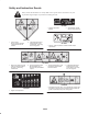
Safety and Instruction Decals Safety decals and instructions are easily visible to the operator and are located near any area of potential danger. Replace any decal that is damaged or lost. 93-6697 1. Read the Operator’s Manual. 2. Add SAE 80w–90 (API GL-5) oil every 50 hours. 106-6753 1. Thrown object hazard—keep bystanders a safe distance from the machine. 2. Cutting/dismemberment hazard of hand or foot, mower blade—stay away from moving parts. 93-7818 1.
107-2908 1. Thrown object hazard—keep bystanders a safe distance from the machine. 2. Thrown object hazard, mower—keep the deflector in place. 3. Cutting/dismemberment hazard of hand or foot, mower blade—stay away from moving parts. 108-1986 1. Height of cut 115-4505 1. Warning—read the Operator’s Manual. 2. Tipping hazard—lower the cutting unit when driving down slopes. For 2 wheel drive units, add a 16 kg (35 lb) rear weight to GM 3280D units and a 32 kg (70 lb) rear weight to GM 3320 units.
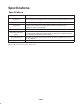
Specifications Specifications Width of cut 60 in. or 72 in. width of cut, 3 blades. Height of cut 1–5 in. (25–127 mm) adjustable in 1/2 in. (13 mm) increments. Height of cut adjustment is achieved by changing spacers on castor wheels and length of height of cut rod. Construction Housing is made of 7 gauge steel and reinforced with channels and plates. Cutter drive Isolation mounted gear box on cutting unit is driven by a PTO shaft. Power is transmitted to the blades by one belt.
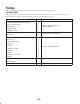
Setup Note: Determine the left and right sides of the machine from the normal operating position. Loose Parts Note: Use this chart as a checklist to ensure that all parts necessary for assembly have been received. Without these parts, total setup cannot be completed. Some parts may have already been assembled at the factory. Description Qty. Discharge deflector assembly (rubber) 1 Screw, 5/16 x 7–1/2 in.
2. Install the bolt and nut. Place the right hand J hook end of the spring around the grass deflector (Fig. 1). Danger Important The grass deflector must be able to lower down into position. Lift the deflector up to test that it lowers into the full down position. If the engine is started and the PTO shaft is allowed to rotate, serious injury could result. Do not start the engine and engage the PTO lever when the PTO shaft is not connected to the gear box on the cutting unit.
Connecting the Lift Arms to the Cutting Unit 6. Push down on the rear of the cutting unit and insert the height of cut rods through the lift arm pads. 7. Install the height of cut collars onto the height of cut rods and secure with the clevis pins and hair pin cotters (Fig. 3). Position the head of the clevis pin toward the front of the deck, if possible. 1. Move the cutting unit into position in front of the traction unit. 2. Move the lift lever to the Float position.
Before Operating 1. Start the engine and raise the cutting unit off the floor so that the height-of-cut can be changed. Stop the engine and remove the key after the cutting unit is raised. Caution 2. Position the castor wheel axles in the same holes in both castor forks. Refer to figure 7 to determine the correct holes for the setting. If you leave the key in the ignition switch, someone could accidently start the engine and seriously injure you or other bystanders.
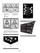
7. Secure the adjustment with the clevis pin and hair pin. Note: Position the head of the clevis pin toward the front of the deck, if possible. Note: When using 1 in. (25 mm), 1-1/2 in. (38 mm), or occasionally 2 in. (51 mm) height–of–cut, move the skids and roller to the highest holes. Adjust the Cutting Unit Pitch Figure 7 Measuring the Cutting Unit Pitch Cutting unit pitch is the difference in height-of-cut from the front of the blade plane to the back of the blade plane.
Adjusting the Skids 2. Select a hole so the anti–scalp roller is positioned to the nearest corresponding height-of-cut desired (Fig. 13). The skids should be mounted in the lower position when operating in height of cuts greater than 2-1/2 inches (64 mm) and in the higher position when operating in height of cuts lower than 2-1/2 inches (64 mm). Adjust the skids by removing the flange bolt and nuts, positioning them as desired, and installing the fasteners (Fig. 11). Figure 13 3.
To adjust the rear (internal) rollers (Fig. 15) 2. Adjust the baffle and cam locks in the slots to the desired discharge flow. 1. Remove the lock nuts securing the roller shafts to the underside of the deck. 3. Swing the lever back over to tighten the baffle and cam locks. 4. If the cams do not lock the baffle into place or it is too tight, loosen the lever and then rotate the cam lock. Adjust the cam lock until the desired locking pressure is achieved.
Position B 3. Check and adjust all castor tire pressures to 50 psi (345 kPa). Use this position when bagging. 4. Check for bent blades; refer to Checking for a Bent Blade, page 23. Middle Position 5. Cut grass in a test area to determine if all cutting units are cutting at the same height. 6. If cutting unit adjustments are still needed, find a flat surface using a 6 foot (2 m) or longer straight edge. 7.
Operation to maintain the same height-of-cut, which is a good practice, you will need to cut more frequently in early spring; as the grass growth rate slows in mid summer, cut only every 8–10 days. If you are unable to mow for an extended period due to weather conditions or other reasons, mow first with the height-of-cut at a high level; then mow again 2–3 days later with a lower height setting. Note: Determine the left and right sides of the machine from the normal operating position.
Maintenance Recommended Maintenance Schedule Maintenance Service Interval Maintenance Procedure After first 2 hours • Tighten the castor wheel nuts. After first 10 hours • Tighten the castor wheel nuts. • Torque the blade bolts. • Check the blades. • Lubricate the castor arm bushings.1 • Lubricate the castor wheel bearings.1 Daily Tighten the castor wheel nuts. Torque the blade bolts. Lubricate the grease fittings.1 Clean under the cutting unit belt covers. Check the blade drive belt adjustment.
2. Position the machine and cutting unit on a level surface and lower the cutting unit. Remove the dipstick/fill plug from the top of the gear box (Fig. 25) and make sure that the lubricant is between the marks on the dipstick. If the lubricant level is low, add SAE 80–90 wt. gear lube until the level is between the marks. 1 Figure 22 Figure 25 1.
Separating the Cutting Unit from the Traction Unit 5. Roll the cutting unit away from the traction unit, separating the male and female sections of the PTO shaft (Fig. 28). 1. Position the machine on level surface, lower the cutting unit to the floor, move the lift lever to the Float position, shut the engine off, and engage the parking brake. 2. Remove the capscrew and washer mounted to the top of each height of cut rod (Fig. 8). 3.
8 10 1 7 6 Servicing the Castor Arm Bushings 11 9 The castor arms have bushings pressed into the top and bottom of the tube and after many hours of operation, the bushings will wear. To check the bushings, move the castor fork back and forth and from side to side. If the castor spindle is loose inside the bushings, the bushings are worn and must be replaced. 4 5 1. Raise the cutting unit so that the wheels are off of the floor. Block the cutting unit so that it cannot accidentally fall. 3 2.
2. Remove the bearing from the wheel hub and allow the bearing spacer to fall out (Fig. 31). Remove the bearing from the opposite side of the wheel hub. 3. Rotate the opposite end of the blade forward. Measure between the cutting unit and cutting edge of the blade at the same position as in step 2. The difference between the dimensions obtained in steps 2 and 3 must not exceed 1/8 in. (3 mm). If the dimension exceeds 1/8 in.
FLAT PART OF BLADE Important The curved part of the blade must be pointing toward the inside of the cutting unit to ensure proper cutting. A SAIL Inspecting and Sharpening the Cutter Blade(s) SAIL B Danger WEAR A worn or damaged blade can break, and a piece of the blade could be thrown into the operator’s or bystander’s area, resulting in serious personal injury or death. Trying to repair a damaged blade may result in discontinued safety certification of the product.
2. Raise the height-of-cut to the highest position; refer to Adjusting the Height-Of-Cut, page 13. 3. Lower the cutting unit onto the flat surface. Remove the covers from the top of the cutting unit. 1 4. Rotate the blades until the ends face forward and backward. Measure from the floor to the front tip of the cutting edge. Remember this dimension. Then rotate the same blade so that the opposite end is forward, and measure again. The difference between the dimensions must not exceed 1/8 in. (3 mm).
Replacing the Grass Deflector 4. Install the bolt and nut. Place the right hand J hook end of the spring around the grass deflector (Fig. 39). Important The grass deflector must be able to lower down into position. Lift the deflector up to test that it lowers into the full down position. Warning An uncovered discharge opening could allow the lawn mower to throw objects in the operator’s or bystander’s direction and result in serious injury. Also, contact with the blade could occur.
The Toro General Commercial Products Warranty A Two-Year Limited Warranty Conditions and Products Covered The Toro Company and its affiliate, Toro Warranty Company, pursuant to an agreement between them, jointly warrant your Toro Commercial Product (“Product”) to be free from defects in materials or workmanship for two years or 1500 operational hours*, whichever occurs first.