Form No. 3383-235 Rev A 60in Side Discharge Mower Groundsmaster® 3320/3280-D Traction Unit Model No. 30366—Serial No. 314000001 and Up Register at www.Toro.com.
This product complies with all relevant European directives, for details please see the separate product specific Declaration of Conformity (DOC) sheet. Figure 1 WARNING 1. Safety alert symbol CALIFORNIA Proposition 65 Warning This manual uses 2 other words to highlight information. Important calls attention to special mechanical information and Note emphasizes general information worthy of special attention.
Contents Safety Introduction .................................................................. 2 Safety ........................................................................... 3 Safe Operating Practices........................................... 3 Toro Mower Safety .................................................. 5 Safety and Instructional Decals ................................. 6 Setup ............................................................................
• Look behind and down before backing up to be sure of • Extinguish all cigarettes, cigars, pipes, and other sources • • • • • • • • • • of ignition. Use only an approved fuel container. Never remove fuel cap or add fuel with the engine running. Allow engine to cool before refueling. Never refuel the machine indoors. Never store the machine or fuel container where there is an open flame, spark, or pilot light such as on a water heater or on other appliances.
• Make sure that all hydraulic line connectors are tight and • Use full width ramps for loading machine into trailer or all hydraulic hoses and lines are in good condition before applying pressure to the system. truck. • Tie the machine down securely using straps, chains, cable, • Keep your body and hands away from pin hole leaks or or ropes. Both front and rear straps should be directed down and outward from the machine nozzles that eject hydraulic fluid under high pressure.
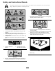
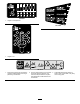
Safety and Instructional Decals Safety decals and instructions are easily visible to the operator and are located near any area of potential danger. Replace any decal that is damaged or lost. 117–4979 1. Entanglement hazard, belt—stay away from moving parts, keep all guards and shields in place. 107-2908 120-6604 1. Thrown object hazard—keep bystanders a safe distance from the machine. 2. Thrown object hazard—do not operate the mower with the deflector up or removed, keep the deflector in place. 1.
100-5622 1. Height of cut adjustment 107-1622 108-1986 1. Height of cut 107-2916 1. Remove the ignition key and read the Operator's Manual before servicing or performing maintenance. 2. Thrown object hazard—do not operate the mower with the deflector up or removed, keep the deflector in place; keep bystanders a safe distance from the machine. 7 3. Cutting/dismemberment hazard of hand or foot, mower blade—stay away from moving parts.
Setup Loose Parts Use the chart below to verify that all parts have been shipped. Procedure Description Use Qty. Pivot pin assembly Cotter pin Lift arm, right Lift arm, left Thrust washer-nylon Clevis pin Hair pin Height of cut collar Clevis pin Hair pin Capscrew, 1/2 x 3/4 inch Washer 2 2 1 1 4 4 2 2 2 2 2 2 3 No parts required – Replace the Traction Unit PTO Shaft (Cutting Unit Model 30366 only) 4 5 No parts required – Connect the PTO shaft to the cutting unit gear box.
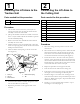
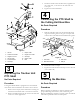
1 2 Installing the Lift Arms to the Traction Unit Connecting the Lift Arms to the Cutting Unit Parts needed for this procedure: Parts needed for this procedure: 2 Pivot pin assembly 1 Lift arm, right 2 Cotter pin 1 Lift arm, left 4 Thrust washer-nylon 4 Clevis pin 1. On one side of the traction unit, loosen (do not remove) the wheel nuts securing the wheel and tire assembly to the front wheel studs. 2 Hair pin 2 Height of cut collar 2 Clevis pin 2.
3. Install the female end of the PTO shaft, supplied with the cutting unit, to the traction unit shaft with the cotter pin. 4. Tighten the bolts and locknuts. 4 Connecting the PTO Shaft to the Cutting Unit Gear Box No Parts Required Procedure 1. Slide the male PTO shaft into the female PTO shaft. Align the mounting holes in the gear case input shaft with the holes in the PTO shaft and slide them together. Figure 3 1. Lift arm 7. Hairpin cotter 2. Castor arm bracket 8. Height-of-cut collar 3.
Product Overview Operation Specifications Note: Determine the left and right sides of the machine from the normal operating position. Note: Specifications and design are subject to change without notice. CAUTION If you leave the key in the ignition switch, someone could accidently start the engine and seriously injure you or other bystanders. Width of 1.52 m (60 inches) Cut Height of Cut Adjustable from 25 to 127 mm (1 to 5 inches) in 13 mm (1/2 inch) increments Net Weight 204 kg (450 lb.
Adjusting the Height-of-Cut 3. Remove the tensioning cap from the spindle shaft (Figure 6) and slide the spindle out of the castor arm. Put the 2 shims (1/8 inch) onto the spindle shaft as they were originally installed. These shims are required to achieve a level across the entire width of the cutting units. Slide the appropriate number of 1/2 inch spacers onto the spindle shaft to get the desired height-of-cut; then slide the washer onto the shaft.
Figure 11 1. Internal rollers Figure 9 Adjusting the Skids The skids should be mounted in the lower position when operating in height of cuts greater than 64 mm (2-1/2 inches) and in the higher position when operating in height of cuts lower than 64 mm (2-1/2 inches). Adjusting the Rollers Note: If the cutting unit is to be used in the 25 or 38 mm (1 or 1-1/2 inch) height-of-cut setting, the cutting unit rollers must be repositioned in the top bracket holes.
lock. Adjust the cam lock until the desired locking pressure is achieved. 1 2 3 4 Figure 15 G008961 Position C Figure 13 1. Unlock lever 2. Rotate the cam lock to increase or decrease locking pressure This is the full open position. The suggested use for this position is as follows. 3. Position the baffle 4. Lock lever • • • • Positioning the Flow Baffle Use in tall, dense grass mowing conditions. Use in wet conditions. Lowers the engine power consumption.
Using the Side Discharge 6. Loosen the jam nuts on the bottom of the height-of-cut rods (Figure 17). The mower has a hinged grass deflector that disperses clippings to the side and down toward the turf. DANGER Without a grass deflector, discharge cover, or complete grass catcher assembly mounted in place, you and others are exposed to blade contact and thrown debris. Contact with rotating mower blade(s) and thrown debris will cause injury or death.
Operating Tips Mow When Grass is Dry Mow either in the late morning to avoid the dew, which causes grass clumping, or in late afternoon to avoid the damage that can be caused by direct sunlight on the sensitive, freshly mowed grass. Select the Proper Height-of-Cut Setting to Suit Conditions Remove approximately 25 mm (1 inch) or no more than 1/3 of the grass blade when cutting. In exceptionally lush and dense grass, you may have to raise the height-of-cut to the next setting.
Maintenance Recommended Maintenance Schedule(s) Maintenance Service Interval Maintenance Procedure After the first 2 hours • Tighten the castor wheel nuts After the first 10 hours • Tighten the castor wheel nuts • Torque the blade bolts Before each use or daily • Lubricate the castor arm bushings • Lubricate the castor wheel bearings • Check the blades Every 50 hours • • • • • • Check the gear box lubricant Lubricate the grease fittings Tighten the castor wheel nuts Torque the blade bolts Check th
Lubrication Service Interval: Every 50 hours The machine has grease fittings that must be lubricated regularly with No. 2 General Purpose Lithium Base Grease. If the machine is operated under normal conditions, lubricate all bearings and bushings after every 50 hours of operation or immediately after every washing. 1.
Pre Maintenance Important: The fasteners on the covers of this machine are designed to remain on the cover after removal. Loosen all of the fasteners on each cover a few turns so that the cover is loose but still attached, then go back and loosen them until the cover comes free. This will prevent you from accidentally stripping the bolts free of the retainers. Separating the Cutting Unit from the Traction Unit Figure 24 1.
Servicing the Bushings in the Castor Arms holes in the castor arm bracket and the height of cut rod can be inserted into the lift arm pads (Figure 26). 5. Secure the lift arm to the castor arm with (2) thrust washers, a clevis pin and a hair pin cotter. Position the thrust washers between the lift arm and the castor arm bracket (Figure 26). Insert end of cotter pin into the slot in the castor arm tab to retain cotter pin.
Removing and Installing the Blade(s) 3. Check the bearings, spacer, and inside of the wheel hub for wear. Replace any damaged parts. 4. To assemble the castor wheel, push the bearing into the wheel hub. When installing the bearings, press on the outer race of the bearing. The blade must be replaced if a solid object is hit, the blade is out-of-balance, worn, or bent. Always use genuine Toro replacement blades to ensure safety and optimum performance.
Inspecting and Sharpening the Blade(s) Service Interval: Before each use or daily Every 50 hours DANGER A worn or damaged blade can break, and a piece of the blade could be thrown into the operator's or bystander's area, resulting in serious personal injury or death. Figure 31 • Inspect the blade periodically for wear or damage. 1. Cutting edge 3. Wear/slot forming 2. Curved area/sail 4. Crack WARNING • Do not try to straighten a blade that is bent.
Checking and Correcting Mismatch of Blades 2. Using a torque wrench or similar tool, move the idler pulley (Figure 33) away from the drive belt to release the belt tension and allow the belt to be slipped off the gearbox pulley (Figure 34). If there is mismatch between the blades, the grass will appear streaked when it is cut. This problem can be corrected by making sure that the blades are straight and all of the blades are cutting on the same plane. 1.
Replacing the Grass Deflector WARNING An uncovered discharge opening could allow the lawn mower to throw objects in the operator's or bystander's direction and result in serious injury. Also, contact with the blade could occur. • Never operate the lawn mower unless you install a cover plate, a mulch plate, or a grass chute and catcher. • Make sure the grass deflector is in the down position. 1. Remove the locknut, bolt, spring and spacer holding the deflector to the pivot brackets (Figure 36).
Notes: 25
Notes: 26
Declaration of Incorporation The Toro Company, 8111 Lyndale Ave. South, Bloomington, MN, USA declares that the following unit(s) conform(s) to the directives listed, when installed in accordance with the accompanying instructions onto certain Toro models as indicated on the relevant Declarations of Conformity. Model No. 30366 Serial No.
The Toro Total Coverage Guarantee A Limited Warranty Conditions and Products Covered The Toro Company and its affiliate, Toro Warranty Company, pursuant to an agreement between them, jointly warrant your Toro Commercial product (“Product”) to be free from defects in materials or workmanship for two years or 1500 operational hours*, whichever occurs first. This warranty is applicable to all products with the exception of Aerators (refer to separate warranty statements for these products).