
Operator's Manual

1
InstallingtheLiftArmstothe
TractionUnit
Partsneededforthisprocedure:
2Pivotpinassembly
2
Cotterpin
Procedure
1.Ononesideofthetractionunit,loosen(donot
remove)thewheelnutssecuringthewheelandtire
assemblytothefrontwheelstuds.
2.Jackupthemachineuntilthefrontwheelisoffofthe
oor.Usejackstandsorblockthemachinetoprevent
itfromaccidentallyfalling.
3.Removethewheelnutsandslidethewheelandtire
assemblyoffofthestuds.
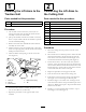
4.Mountaliftarmtothepivotbracketwithapivotpin
andacotterpin(
Figure2).Mounttheliftarmwiththe
bendpositionedoutward.
5.Hookthebrakereturnspringtothetabonthelift
arm(Figure2).
Figure2
1.Pivotpin4.Brakereturnspring
2.Liftarm
5.Tab
3.Pivotbracket
6.Installthewheelandtireassembly.Torquethewheel
nutsto102–108N-m(75–80ft-lb).
7.Repeattheprocedureontheoppositesideofthe
machine.
2
ConnectingtheLiftArmsto
theCuttingUnit
Partsneededforthisprocedure:
1
Liftarm,right
1
Liftarm,left
4Thrustwasher-nylon
4
Clevispin
2Hairpin
2
Heightofcutcollar
2
Clevispin
2Hairpin
2
Capscrew,1/2x3/4inch
2Washer
Procedure
1.Movethecuttingunitintopositioninfrontofthe
tractionunit.
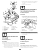
2.MovetheliftlevertotheFloatposition.Pushaliftarm
downuntiltheholesintheliftarmlineupwiththe
holesinthecastorarmbracketandtheheightofcut
rodcanbeinsertedintotheliftarmpads(Figure3).
3.Securetheliftarmtothecastorarmwith(2)thrust
washers,aclevispinandahairpincotter.Positionthe
thrustwashersbetweentheliftarmandthecastorarm
bracket(Figure3).Insertendofcotterpinintotheslot
inthecastorarmtabtoretaincotterpin.
4.Repeattheprocedureontheoppositeliftarm.
5.Startthetractionunitandraisethecuttingunit.
6.Pushdownontherearofthecuttingunitandinsert
theheightofcutrodsthroughtheliftarmpads.
7.Installtheheightofcutcollarsontotheheightofcut
rodsandsecurewiththeclevispinsandhairpincotters
(Figure3).Headofclevispintobepositionedtoward
thefrontofthedeck.
8.Installa1/2x3/4inchboltandawashertotopof
eachheightofcutrod(Figure3).
9