Form No. 3430-203 Rev A 60in Side Discharge Mower Groundsmaster® 3320/3280-D Traction Unit Model No. 30366—Serial No. 403360001 and Up Register at www.Toro.com.
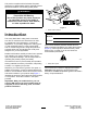
This product complies with all relevant European directives, for details please see the separate product specific Declaration of Conformity (DOC) sheet. WARNING CALIFORNIA Proposition 65 Warning Use of this product may cause exposure to chemicals known to the State of California to cause cancer, birth defects, or other reproductive harm. g243406 Figure 1 1. Serial number location Introduction Model No.
Contents Safety Safety ....................................................................... 3 General Safety ................................................... 3 Cutting Unit Safety.............................................. 3 Safety and Instructional Decals .......................... 4 Setup ........................................................................ 7 1 Installing the Lift Arms to the Traction Unit .................................................................
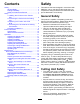
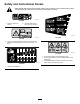
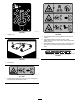
Safety and Instructional Decals Safety decals and instructions are easily visible to the operator and are located near any area of potential danger. Replace any decal that is damaged or missing. decal93-6697 93-6697 1. Read the Operator's Manual. 2. Add SAE 80w-90 (API GL-5) oil every 50 hours. decal107-1622 107-1622 decal93-7818 93-7818 1. Warning—read the Operator's Manual for instructions on torquing the blade bolt/nut to 115 to 149 N∙m (85 to 110 ft-lb). decal107-2908 107-2908 1.
decal108-1986 108-1986 decal120-6604 120-6604 1. Height of cut 1. Thrown object hazard—keep bystanders away from the machine. 2. Cutting/dismemberment hazard of hand, mower blade—stay away from moving parts, keep all guards and shields in place. 3. Cutting/dismemberment hazard of foot, mower blade—stay away from moving parts, keep all guards and shields in place. decal133-8061 133-8061 decal108-1988 108-1988 1. Belt routing decal117-4979 117–4979 1.
decal107-2916 107-2916 1. Remove the key and read the Operator's Manual before performing maintenance. 2. Thrown object hazard—do not operate the mower with the deflector up or removed; lower the deflector before using the machine; keep bystanders away. 6 3. Cutting/dismemberment hazard of hand or foot, mower blade—stay away from moving parts.
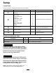
Setup Loose Parts Use the chart below to verify that all parts have been shipped. Procedure Description Use Qty. Pivot pin assembly Cotter pin Lift arm, right Lift arm, left Thrust washer-nylon Clevis pin Hairpin cotter—small Height of cut collar Clevis pin Hairpin cotter—large Bolt (1/2 x 3/4 inch) Washer 2 2 1 1 4 4 2 2 2 2 2 2 3 No parts required – Replace the traction unit PTO shaft (cutting unit model 30366 only). 4 5 No parts required – Connect the PTO shaft to the cutting unit gearbox.
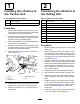
1 2 Installing the Lift Arms to the Traction Unit Connecting the Lift Arms to the Cutting Unit Parts needed for this procedure: Parts needed for this procedure: 2 Pivot pin assembly 1 Lift arm, right 2 Cotter pin 1 Lift arm, left 4 Thrust washer-nylon 4 Clevis pin 2 Hairpin cotter—small 2 Height of cut collar 2 Clevis pin 2 Hairpin cotter—large 2 Bolt (1/2 x 3/4 inch) 2 Washer Procedure 1. 2.
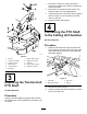
1. Remove the cotter pin, bolts and locknuts securing the female end of the PTO shaft to the traction unit shaft. 2. Remove the PTO shaft from the traction unit shaft and retain it for future applications. 3. Install the female end of the PTO shaft, supplied with the cutting unit, to the traction unit shaft with the cotter pin. 4. Tighten the bolts and locknuts. 4 Connecting the PTO Shaft to the Cutting Unit Gearbox No Parts Required Procedure 1. Slide the male PTO shaft into the female PTO shaft.
Product Overview 5 Specifications Greasing the Machine Note: Specifications and design are subject to change without notice. No Parts Required Width of Cut 1.52 m (60 inches) Procedure Height of Cut Adjustable from 25 to 127 mm (1 to 5 inches) in 13 mm (1/2 inch) increments Before operating the machine, it must be greased to ensure proper lubricating characteristics; refer to Lubrication (page 18). Failure to properly grease the machine will result in premature failure of critical parts.
Operation Note: Determine the left and right sides of the machine from the normal operating position. CAUTION If you leave the key in the ignition switch, someone could accidently start the engine and seriously injure you or other bystanders. decal100-5622 Figure 7 Remove the key from the ignition before you do any maintenance.
Adjusting the Rollers Note: If the cutting unit is to be used in the 25 or 38 mm (1 or 1-1/2 inch) height-of-cut setting, the cutting unit rollers must be repositioned in the top bracket holes. 1. To adjust the front rollers, remove the screw and nut securing the roller shaft to the deck bracket (Figure 10). g012231 Figure 8 1. Height-of-cut rod 3. Clevis pin and hairpin cotter 2. Height-of-cut collar 6.
Adjusting the Skids Adjusting the Flow Baffle Mount the skids in the lower position when operating in height of cuts higher than 64 mm (2-1/2 inches) and in the higher position when operating in height of cuts lower than 64 mm (2-1/2 inches). The mower discharge flow can be adjusted for different types of mowing conditions. Position the cam locks and baffle to give the best quality of cut. 1. To adjust the cam locks, swing the lever up to loosen the cam lock (Figure 13). 2.
Adjusting the Cutting Unit Pitch Cutting unit pitch is the difference in height of cut from the front of the blade plane to the back of the blade plane. Use a blade pitch of 6 mm (1/4 inch), meaning that the back of the blade plane is 6 mm (1/4 inch) higher than the front. 1. Position the machine on a level surface on the shop floor. 2. Set the cutting unit to the desired height of cut. 3. Rotate 1 blade so that it points straight forward. 4.
Correcting a Cutting Unit Mismatch DANGER Without a grass deflector, discharge cover, or complete grass catcher assembly mounted in place, you and others are exposed to blade contact and thrown debris. Contact with rotating mower blade(s) and thrown debris will cause injury or death. Due to differences in grass conditions and the counterbalance setting of the traction unit, it is advised that grass be cut and appearance checked before formal cutting is started. 1.
Operating Tips inside the cutting unit, cutting quality will eventually become unsatisfactory. Fast Throttle Setting/Ground Speed To reduce the risk of fire hazard, keep the engine, muffler, battery compartment, parking brake, cutting units, and fuel storage compartment free of grass, leaves, or excessive grease. Clean up any spilled oil or fuel. To maintain enough power for the machine and deck while mowing, operate the engine at the fast throttle position and adjust your ground speed for conditions.
Maintenance Recommended Maintenance Schedule(s) Maintenance Service Interval Maintenance Procedure After the first 2 hours • Tighten the castor wheel nuts. After the first 10 hours • Tighten the castor wheel nuts. Before each use or daily • Lubricate the castor arm bushings. • Lubricate the castor wheel bearings. After each use • Clean the cutting unit. Every 50 hours • • • • • Every 400 hours • Change the gearbox lubricant. Lubricate the grease fittings. Check the gearbox lubricant.
Important: The fasteners on the covers of this machine are designed to remain on the cover after removal. Loosen all the fasteners on each cover a few turns so that the cover is loose but still attached, then go back and loosen them until the cover comes free. This prevents you from accidentally stripping the bolts free of the retainers. Lubrication Service Interval: Every 50 hours The machine has grease fittings that must be lubricated regularly with No. 2 lithium grease.
g012237 Figure 24 g010548 1. Lift arm 3. Hairpin cotter 2. Clevis pin 4. Castor arm bracket Figure 22 5. 1. Dipstick/fill plug Roll the cutting unit away from the traction unit, separating the male and female sections of the PTO shaft (Figure 25). Separating the Cutting Unit from the Traction Unit 1. Position the machine on level surface, lower the cutting unit to the floor, move the lift lever to the FLOAT position, shut off the engine, and engage the parking brake. 2.
4. is loose inside the bushings, the bushings are worn; replace them. 1. Raise the cutting unit so that the wheels are off of the floor. Block the cutting unit so that it cannot accidentally fall. 2. Remove the tensioning cap, spacer(s), and thrust washer from the top of the castor spindle. 3. Pull the castor spindle out of the mounting tube. Allow the thrust washer and spacer(s) to remain on the bottom of the spindle. 4.
1. Position the machine on a level surface, raise the cutting unit, engage the parking brake, put the traction pedal in NEUTRAL, put the PTO lever in the OFF position, shut off the engine, and remove the ignition key. Note: Block the cutting unit to prevent it from accidentally falling. 2. Rotate the blade until the ends face forward and backward and measure from the inside of the cutting unit to the cutting edge at the front of the blade (Figure 28). g004741 Figure 29 1.
Note: Remove the blades and sharpen them on a grinder. After sharpening the cutting edges, install the blade with the anti-scalp cup and blade bolt; refer to Removing and Installing the Cutting-Unit Blade(s) (page 21). g004653 Figure 30 1. Cutting edge 3. Wear/slot forming 2. Curved area 4. Crack 3. Examine the cutting edges of all of the blades and sharpen the cutting edges if they are dull or nicked (Figure 31).
Replacing the Drive Belt Checking and Correcting Mismatch of Blades The blade drive belt, tensioned by the spring loaded idler pulley, is very durable. However, after many hours of use, the belt will show signs of wear. Signs of a worn belt are squealing when belt is rotating, blades slipping when cutting grass, frayed edges, burn marks, and cracks. Replace the belt if any of these conditions occur. If there is mismatch between the blades, the grass will appear streaked when it is cut.
decal108-1988 Figure 34 1. Belt routing 5. g000977 Figure 35 Install the belt covers. Replacing the Grass Deflector 1. Bolt 5. Spring installed 2. Spacer 6. Grass deflector 3. Locknut 7. L-end of spring, place behind the cutting unit edge before installing bolt 4. Spring 8. J-hook end of the spring WARNING Cleaning Under the Cutting Unit An uncovered discharge opening could allow the machine to throw objects toward you or bystanders, resulting in serious injury.
Storage 1. Disengage the PTO, release the traction pedal to the neutral position, lower the cutting unit, move the throttle lever to the SLOW position, and engage the parking brake. 2. Always shut off the engine, and remove the key. Wait for all movement to stop and allow the machine to cool before adjusting, cleaning, storing, or repairing it. 3.
Declaration of Incorporation The Toro Company, 8111 Lyndale Ave. South, Bloomington, MN, USA declares that the following unit(s) conform(s) to the directives listed, when installed in accordance with the accompanying instructions onto certain Toro models as indicated on the relevant Declarations of Conformity. Model No. 30366 Serial No.
California Proposition 65 Warning Information What is this warning? You may see a product for sale that has a warning label like the following: WARNING: Cancer and Reproductive Harm—www.p65Warnings.ca.gov. What is Prop 65? Prop 65 applies to any company operating in California, selling products in California, or manufacturing products that may be sold in or brought into California.
The Toro Warranty Two-Year or 1,500 Hours Limited Warranty Conditions and Products Covered Parts The Toro Company and its affiliate, Toro Warranty Company, pursuant to an agreement between them, jointly warrant your Toro Commercial product (“Product”) to be free from defects in materials or workmanship for 2 years or 1,500 operational hours*, whichever occurs first. This warranty is applicable to all products with the exception of Aerators (refer to separate warranty statements for these products).