Form No. 3353–296 Rev B 72 in Guardian Recycler Mower 62 in Guardian Recycler Mower 72 in Rear Discharge Mower 62 in Rear Discharge Mower Groundsmaster 3320 and 3280–D Model No. 30379—Serial No. 250000001 and Up Model No. 30376—Serial No. 250000001 and Up Model No. 30369—Serial No. 250000001 and Up Model No. 30367—Serial No.
Introduction Warning Read this manual carefully to learn how to operate and maintain your product properly. The information in this manual can help you and others avoid injury and product damage. Although Toro designs and produces safe products, you are responsible for operating the product properly and safely. CALIFORNIA Proposition 65 Warning Diesel engine exhaust and some of its constituents are known to the State of California to cause cancer, birth defects, and other reproductive harm.
• Thoroughly inspect the area where the equipment is to be used and remove all objects which may be thrown by the machine. CAUTION, WARNING, or DANGER—“personal safety instruction.” Failure to comply with the instruction may result in personal injury or death. • Warning—fuel is highly flammable. Take the following precautions: Safe Operating Practices – Store fuel in containers specifically designed for this purpose.
– The machine speed should be kept low on slopes and during tight turns. • Disengage drive to attachments when transporting or not is use. – Stay alert for humps and hollows and other hidden hazards. • Stop the engine and disengage drive to attachment: – before refuelling; – Never mow across the face of the slope, unless the machine is designed for that purpose. – before making height adjustment unless adjustment can be made from the operator’s position.
• Shut off fuel while storing or transporting. Do not store fuel near flames. • Wearing safety shoes and long pants is advisable and required by some local ordinances and insurance regulations. • Park machine on level ground. Never allow untrained personnel to service machine. • Use jack stands to support components when required. • Keep hands, feet, and clothing away from moving parts and the mower discharge area and underside of the mower while the engine is running.
Maintenance and Storage • If the engine must be running to perform a maintenance adjustment, keep hands, feet, clothing, and any parts of the body away from the cutting units, attachments, and any moving parts. Keep everyone away. • Do not touch equipment or attachment parts which may be hot from operation. Allow to cool before attempting to maintain, adjust, or service. • Check brake operation frequently. Adjust and service as required.
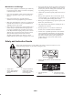
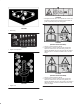
100-6578 1. Entanglement hazard, belt—do not operate the machine with the shields or guards removed; always keep the shields and guards in place. Stay away from moving parts. 108-1988 1. Belt routing 108-5297 (Models 30376 and 30367) 1. Warning—read the Operator’s Manual. 2. Tipping hazard—lower the cutting unit when driving down slopes. For 2 wheel drive units, add a 80 kg (170 lb) rear weight to GM 3280D units and a 92 kg (205 lb) rear weight to GM 3320 units.
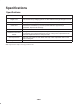
Specifications Specifications Width of cut 62 in. or 72 in. width of cut, 3 blades. Height of cut 1–5 in. (25–177 mm) adjustable in 1/2 in. (13 mm) increments. Height of cut adjustment is achieved by changing spacers on castor wheels and length of height of cut rod. Construction Housing is made of 7 gauge steel and reinforced with channels and plates. Cutter drive Isolation mounted gear box on cutting unit is driven by a PTO shaft. Power is transmitted to the blades by one belt.
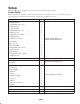
Setup Note: Determine the left and right sides of the machine from the normal operating position. Loose Parts Note: Use this chart as a checklist to ensure that all parts necessary for assembly have been received. Without these parts, total setup cannot be completed. Some parts may have already been assembled at the factory. Description Qty. Rubber deflector 1 Carriage bolt, 5/16 x 1– in. 2 Flange nut, 5/16 2 L.H. Foot shield 1 Carriage bolt, 5/16 x 1 in.
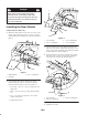
Danger 1 If the engine is started and the PTO shaft is allowed to rotate, serious injury could result. Do not start the engine and engage the PTO lever when the PTO shaft is not connected to the gear box on the cutting unit. Installing the Rear Shields 2 (Models 30369 and 30367 only) 3 1. Mount the rubber deflector to the left rear corner of the cutting with a hold down, (2) 5/16 x 1 in. lg. carriage bolts and flange nuts. Position the deflector as shown in figure 1. 4 Figure 2 1. L.H. foot shield 2.
6. Mount the rear deflector to the rear of the cutting unit with (3) 5/16 x 1–1/4 in. lg. carriage bolts and flange nuts. Position the deflector as shown in figure 4. 2. Slide the spacers onto the castor spindle to get the desired height-of-cut; refer to figure 11 to determine the combinations of spacers for the setting.. Slide a thrust washer onto the spindle, push the castor spindle through the castor arm.
Connecting the Lift Arms to the Cutting Unit 6. Push down on the rear of the cutting unit and insert the height of cut rods through the lift arm pads. 7. Install the height of cut collars onto the height of cut rods and secure with the clevis pins and hair pin cotters (Fig. 7). Position the head of the clevis pin toward the front of the deck, if possible. 1. Move the cutting unit into position in front of the traction unit. 2. Move the lift lever to the Float position.
Before Operating 1. Start the engine and raise the cutting unit off the floor so that the height-of-cut can be changed. Stop the engine and remove the key after the cutting unit is raised. Caution 2. Position the castor wheel axles in the same holes in both castor forks. Refer to figure 11 to determine the correct holes for the setting. If you leave the key in the ignition switch, someone could accidently start the engine and seriously injure you or other bystanders.
Figure 11 4. Push the castor spindle through the castor arm. Install the shims (as they were originally installed) and the remaining spacers onto the spindle shaft. Install the tensioning cap to secure the assembly. 5. Remove the hair pin and clevis pin securing the height of cut collar to the height of cut rod on the rear of the cutting unit (Fig. 12). Figure 13 Note: When using 1 in. (25 mm), 1-1/2 in. (38 mm), or occasionally 2 in. (51 mm) height–of–cut, move the skids and roller to the highest holes.
Adjusting the Rollers 8. Lower cutting unit onto the flat surface. Remove the covers from the top of the cutting units Note: If the cutting unit is to be used in the 1 or 1-1/2 in. (25 or 38 mm) height-of-cut setting, the cutting unit rollers must be repositioned in the top bracket holes. 9. Rotate the blade on each spindle until the ends face forward and backward. 10. Measure from the floor to the front tip of the cutting edge. 1.
Operation Always Mow with Sharp Blades A sharp blade cuts cleanly and without tearing or shredding the grass blades like a dull blade. Tearing and shredding causes the grass to turn brown at the edges which impairs growth and increases susceptibility to diseases. Note: Determine the left and right sides of the machine from the normal operating position. Operating Tips After Operating Mow When Grass is Dry To ensure optimum performance, clean the underside of the mower housing after each use.
Maintenance Recommended Maintenance Schedule Maintenance Service Interval Maintenance Procedure After first 2 hours • Tighten the castor wheel nuts. After first 10 hours • Tighten the castor wheel nuts. • Torque the blade bolts. Daily • Check the blades. • Lubricate the castor arm bushings.1 • Lubricate the castor wheel bearings.1 Tighten the castor wheel nuts. Torque the blade bolts. Lubricate the grease fittings.1 Clean under the cutting unit belt covers. Check the blade drive belt adjustment.
Caution If you leave the key in the ignition switch, someone could accidentally start the engine and seriously injure you or other bystanders. Remove the key from the ignition switch before you do any maintenance. Figure 18 Greasing the Bearings, Bushings and Gear Box The machine has grease fittings that must be lubricated regularly with No. 2 General Purpose Lithium Base Grease.
2. Position the machine and cutting unit on a level surface and lower the cutting unit. Remove the dipstick/fill plug from the top of the gear box (Fig. 21) and make sure that the lubricant is between the marks on the dipstick. If the lubricant level is low, add SAE 80–90 wt. gear lube until the level is between the marks. 3. Remove the hairpin and clevis pin securing the height of cut collar to the height of cut rod on the rear of the cutting unit (Fig. 22). Remove the height of cut collar. 4.
Mounting the Cutting Unit to the Traction Unit 7. Start the traction unit and raise the cutting unit. 8. Push down on the rear of the cutting unit and insert the height of cut rods through the lift arm pads. 1. Position the machine on a level surface and shut the engine off. 2. Move the cutting unit into position in front of the traction unit. 9. Install the height of cut collars onto the height of cut rods and secure with the clevis pins and hair pin cotters (Fig. 25).
Servicing the Castor Arm Bushings 2. Remove the bearing from the wheel hub and allow the bearing spacer to fall out (Fig. 28). Remove the bearing from the opposite side of the wheel hub. The castor arms have bushings pressed into the top and bottom of the tube and after many hours of operation, the bushings will wear. To check the bushings, move the castor fork back and forth and from side to side. If the castor spindle is loose inside the bushings, the bushings are worn and must be replaced. 3.
3. Rotate the opposite end of the blade forward. Measure between the cutting unit and cutting edge of the blade at the same position as in step 2. The difference between the dimensions obtained in steps 2 and 3 must not exceed 1/8 in. (3 mm). If the dimension exceeds 1/8 in. (3 mm), the blade is bent and must be replaced; refer to Removing the Cutter Blade, page 22. Important The curved part of the blade must be pointing toward the inside of the cutting unit to ensure proper cutting.
Correcting Cutting Unit Mismatch Note: Remove the blades and sharpen them on a grinder. After sharpening the cutting edges, install the blade with the anti-scalp cup and blade bolt; refer to Removing and Installing the Cutter Blade(s), page 22. If there is mismatch between the blades, the grass will appear streaked when it is cut. This problem can be corrected by making sure that the blades are straight and all of the blades are cutting on the same plane. FLAT PART OF BLADE A SAIL 1.
Replacing the Drive Belt 4. Route the new belt around the spindle pulleys and idler pulley assembly as shown in figure 35. The blade drive belt, tensioned by the spring loaded idler pulley, is very durable. However, after many hours of use, the belt will show signs of wear. Signs of a worn belt are: squealing when belt is rotating, blades slipping when cutting grass, frayed edges, burn marks and cracks. Replace the belt if any of these conditions are evident. 1. Lower the cutting unit to the shop floor.
Notes 25
Notes 26
Notes 27
The Toro General Commercial Products Warranty A Two-Year Limited Warranty Conditions and Products Covered The Toro Company and its affiliate, Toro Warranty Company, pursuant to an agreement between them, jointly warrant your Toro Commercial Product (“Product”) to be free from defects in materials or workmanship for two years or 1500 operational hours*, whichever occurs first.