
Operator's Manual

10
Danger
If the engine is started and the PTO shaft is
allowed to rotate, serious injury could result.
Do not start the engine and engage the PTO lever
when the PTO shaft is not connected to the gear
box on the cutting unit.
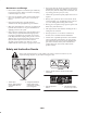
Installing the Rear Shields
(Models 30369 and 30367 only)
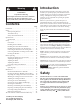
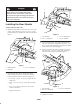
1. Mount the rubber deflector to the left rear corner of the
cutting with a hold down, (2) 5/16 x 1 in. lg. carriage
bolts and flange nuts. Position the deflector as shown in
figure 1.
1
2
3
Figure 1
1. Rubber deflector
2. Hold down
3. 5/16 x 1” carriage bolt
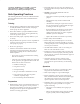
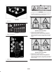
2. Loosely mount the L.H. foot shield to the rubber
deflector using the fasteners and locations detailed
below. Position the fasteners as shown in figure 2.
• Front edge – (2) 5/16 x 1 in. lg. carriage bolts and
flange nuts.
• Side – (1) 1/4 x 3/4 in. lg. carriage bolt and flange
nut.
• Top – 1/4 x 3/4 in. lg. capscrew, 5/16 x 3/4 flat
washer and locknut.
• Tighten the fasteners.
1
2
3
4
Figure 2
1. L.H. foot shield
2. 5/16 x 1” carriage bolt
3. 1/4 x 3/4” carriage bolt
4. 1/4 x 3/4” capscrew
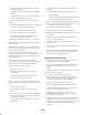
3. Loosely mount the side of the R.H. foot shield to the
right rear corner of the cutting unit with (2) 5/16 x 3/4
in. lg. carriage bolts and flange nuts. Position the shield
and the fasteners as shown in figure 3.
4. Loosely mount the top of the foot shield to the cutting
unit with a 5/16 x 3/4 in. lg. carriage bolt and flange
nut. Position the fasteners as shown in figure 3.
1
2
3
Figure 3
1. R.H. foot shield
2. 5/16 x 3/4” carriage bolt
3. 5/16 x 3/4” carriage bolt
5. Tighten the fasteners.