Form No. 3371-654 Rev A 72in Side Discharge Mower Groundsmaster® 3320/3280-D Traction Unit Model No. 30368—Serial No. 311000301 and Up To register your product or download an Operator's Manual or Parts Catalog at no charge, go to www.Toro.com.
Contents This product complies with all relevant European directives, for details please see the separate product specific Declaration of Conformity (DOC) sheet. Introduction................................................................. 2 Safety ........................................................................... 3 Safe Operating Practices ....................................... 3 Toro Mower Safety ............................................... 4 Safety and Instructional Decals ................
Safety – Use only an approved container. – Never remove fuel cap or add fuel with engine running. Allow engine to cool before refueling. Do not smoke while refueling. This machine meets or exceeds CEN standard EN 836:1997, ISO standard 5395:1990, and ANSI B71.4-2004 specifications in effect at the time of production. – Never refuel or drain the machine indoors. • Check that operator's presence controls, safety switches and shields are attached and functioning properly.
Toro Mower Safety • Do not operate the mower under the influence of alcohol or drugs. • Lightning can cause severe injury or death. If lightning is seen or thunder is heard in the area, do not operate the machine; seek shelter. • Use care when loading or unloading the machine into a trailer or truck. • Use care when approaching blind corners, shrubs, trees, or other objects that may obscure vision.
• Keep your body and hands away from pin hole leaks or nozzles that eject hydraulic fluid under high pressure. Use paper or cardboard, not your hands, to search for leaks. Hydraulic fluid escaping under pressure can have sufficient force to penetrate the skin and cause serious injury. • Before disconnecting or performing any work on the hydraulic system, all pressure in the system must be relieved by stopping the engine and lowering the cutting units to the ground.
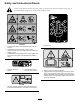
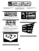
Safety and Instructional Decals Safety decals and instructions are easily visible to the operator and are located near any area of potential danger. Replace any decal that is damaged or lost. 108-1986 120-6604 1. Height of cut 1. Thrown object hazard—keep bystanders away from the machine. 2. Cutting/dismemberment hazard of hand, mower blade—stay away from moving parts, keep all guards and shields in place. 3.
107-2916 1. Remove the ignition key and read the Operator's Manual before servicing or performing maintenance. 2. Thrown object hazard—do not operate the mower with the deflector up or removed, keep the deflector in place; keep bystanders a safe distance from the machine. 3. Cutting/dismemberment hazard of hand or foot, mower blade—stay away from moving parts. 117–4979 1. Entanglement hazard, belt—stay away from moving parts, keep all guards and shields in place. 100-5622 1.
Setup Loose Parts Use the chart below to verify that all parts have been shipped. Procedure Description 1 2 3 4 5 Use Qty.
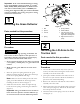
Important: If the 72 inch Side Discharge Cutting Unit, model 30368, is being mounted to a model 30307, 30308, 30309, 30343, 30344 or 30345 traction unit with a serial number prior to 311000301, the Cutting Unit Alignment Kit, part number 120–6599 must be installed to the cutting unit prior to being mounted to traction unit.
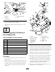
Figure 3 1. Pivot pin 4. Brake return spring 2. Lift arm 3. Pivot bracket 5. Tab 6. Install the wheel and tire assembly. Torque the wheel nuts to 75–80 ft-lb (102–108 N-m). 7. Repeat the procedure on the opposite side of the machine.
Product Overview 4 Specifications Connecting the PTO Shaft to the Cutting Unit Gear Box Note: Specifications and design are subject to change without notice. Width of 72 inches (1.829 m) Cut No Parts Required Procedure 1. Slide the male PTO shaft into the female PTO shaft. Align the mounting holes in the gear case input shaft with the holes in the PTO shaft and slide them together. Height of Cut Adjustable from 1 to 5 inches (25 to 127 mm) in 1/2 inch (13 mm) increments Net Weight 600 lb.
Adjusting the Height-of-Cut Operation The height-of-cut is adjustable from 1 to 5 inches (25 to 127 mm) in 1/2 inch (13 mm) increments. To adjust the height-of-cut, position the castor wheel axles in the upper or lower holes of the castor forks, add or remove an equal number of spacers from the castor forks and secure the height of cut collar to the desired holes in the height of cut rod. 1. Start the engine and raise the cutting unit off the floor so that the height-of-cut can be changed.
reverse the machines direction to pull any clippings away from the wheel/fork area. 3. Remove the tensioning cap from the spindle shaft (Figure 7) and slide the spindle out of the castor arm. Put the 2 shims (1/8 inch) onto the spindle shaft as they were originally installed. These shims are required to achieve a level across the entire width of the cutting units. Slide the appropriate number of 1/2 inch spacers onto the spindle shaft to get the desired height-of-cut; then slide the washer onto the shaft.
Adjusting the Anti-Scalp Rollers 2. Slide the shaft out of the lower bracket holes, align the roller with the top holes, and install the shaft. 3. Install the screw and nut to secure the assemblies. Whenever you change the height-of-cut, it is recommended to adjust the height of the anti-scalp rollers. To adjust the rear (internal) rollers (Figure 12) 1. After adjusting the height-of-cut, adjust the rollers by removing the flange nut, bushing, spacer, and bolt (Figure 14). Figure 12 1.
1 2 3 4 Figure 17 G008961 Figure 15 1. Unlock lever 2. Rotate the cam lock to increase or decrease locking pressure 3. Position the baffle 4. Lock lever Position C This is the full open position. The suggested use for this position is as follows. • Use in tall, dense grass mowing conditions. Positioning the Flow Baffle • Use in wet conditions. The following figures are only recommendations for use. Adjustments will vary by grass type, moisture content, and height of grass.
5. Subtract the front dimension from the rear dimension to calculate the blade pitch. 9. Rotate the blade on each spindle until the ends face forward and backward. 10. Measure from the floor to the front tip of the cutting edge. 6. Loosen the jam nuts on the bottom of the height-of-cut rods (Figure 19). Using the Side Discharge The mower has a hinged grass deflector that disperses clippings to the side and down toward the turf.
is a good practice, you will need to cut more frequently in early spring; as the grass growth rate slows in mid summer, cut only every 8–10 days. If you are unable to mow for an extended period due to weather conditions or other reasons, mow first with the height-of-cut at a high level; then mow again 2–3 days later with a lower height setting. Always Mow with Sharp Blades A sharp blade cuts cleanly and without tearing or shredding the grass blades like a dull blade.
Maintenance Recommended Maintenance Schedule(s) Maintenance Service Interval Maintenance Procedure After the first 2 hours • Tighten the castor wheel nuts After the first 10 hours • Tighten the castor wheel nuts • Torque the blade bolts Before each use or daily • Lubricate the castor arm bushings • Lubricate the castor wheel bearings • Check the blades Every 50 hours • • • • • • Check the gear box lubricant Lubricate the grease fittings Tighten the castor wheel nuts Torque the blade bolts Check th
Lubrication Service Interval: Every 50 hours The machine has grease fittings that must be lubricated regularly with No. 2 General Purpose Lithium Base Grease. If the machine is operated under normal conditions, lubricate all bearings and bushings after every 50 hours of operation or immediately after every washing. 1. Lubricate the following areas: Figure 22 • Castor fork shaft bushings (2)(Figure 20) • Lift arm pivots, rear (2) (Figure 23) Figure 23 Figure 20 2.
Figure 25 1. Height-of-cut rod 3. Height-of-cut collar 2. Bolt and washer 4. Hairpin cotter and clevis pin Figure 24 1. Dipstick/fill plug 3. Remove the hairpin and clevis pin securing the height of cut collar to the height of cut rod on the rear of the cutting unit (Figure 25). Remove the height of cut collar. Pre Maintenance 4. Remove the hair pin cotters and clevis pins securing the lift arms to the castor arm brackets (Figure 26).
Figure 27 1. PTO shaft DANGER If the engine is started and the PTO shaft is allowed to rotate, serious injury could result. Do not start the engine and engage the PTO lever when the PTO shaft is not connected to the gear box on the cutting unit. Mounting the Cutting Unit to the Traction Unit 1. Position the machine on a level surface and shut the engine off. Figure 28 2. Move the cutting unit into position in front of the traction unit. 3. Slide the male PTO shaft into the female PTO shaft (Figure 27).
Servicing the Bushings in the Castor Arms The castor arms have bushings pressed into the top and bottom of the tube and after many hours of operation, the bushings will wear. To check the bushings, move the castor fork back and forth and from side to side. If the castor spindle is loose inside the bushings, the bushings are worn and must be replaced. 1. Raise the cutting unit so that the wheels are off of the floor. Block the cutting unit so that it cannot accidentally fall. 2.
Inspecting and Sharpening the Blade(s) difference between the dimensions obtained in steps 2 and 3 must not exceed 1/8 inch (3 mm). If the dimension exceeds 1/8 inch (3 mm), replace the blade because it is bent; refer to Removing the Cutting Blade.
Checking and Correcting Mismatch of Blades If there is mismatch between the blades, the grass will appear streaked when it is cut. This problem can be corrected by making sure that the blades are straight and all of the blades are cutting on the same plane. 1. Using a 3 foot (1 meter) long carpenters level, find a level surface on the shop floor. Figure 33 1. Cutting edge 3. Wear/slot forming 2. Curved area/sail 4. Crack 2.
Replacing the Drive Belt The blade drive belt, tensioned by the spring loaded idler pulley, is very durable. However, after many hours of use, the belt will show signs of wear. Signs of a worn belt are: squealing when belt is rotating, blades slipping when cutting grass, frayed edges, burn marks and cracks. Replace the belt if any of these conditions are evident. 1. Lower the cutting unit to the shop floor. Remove the belt covers from the top of the cutting unit and set the covers aside. Figure 37 2.
Figure 38 1. Bolt 5. Spring installed 2. Spacer 6. Grass Deflector 3. Locknut 7. L end of spring, place behind deck edge before installing bolt 4. Spring 8.
Notes: 27
The Toro Total Coverage Guarantee A Limited Warranty Conditions and Products Covered The Toro® Company and its affiliate, Toro Warranty Company, pursuant to an agreement between them, jointly warrant your Toro Commercial product (“Product”) to be free from defects in materials or workmanship for two years or 1500 operational hours*, whichever occurs first. This warranty is applicable to all products with the exception of Aerators (refer to separate warranty statements for these products).