
Operator's Manual


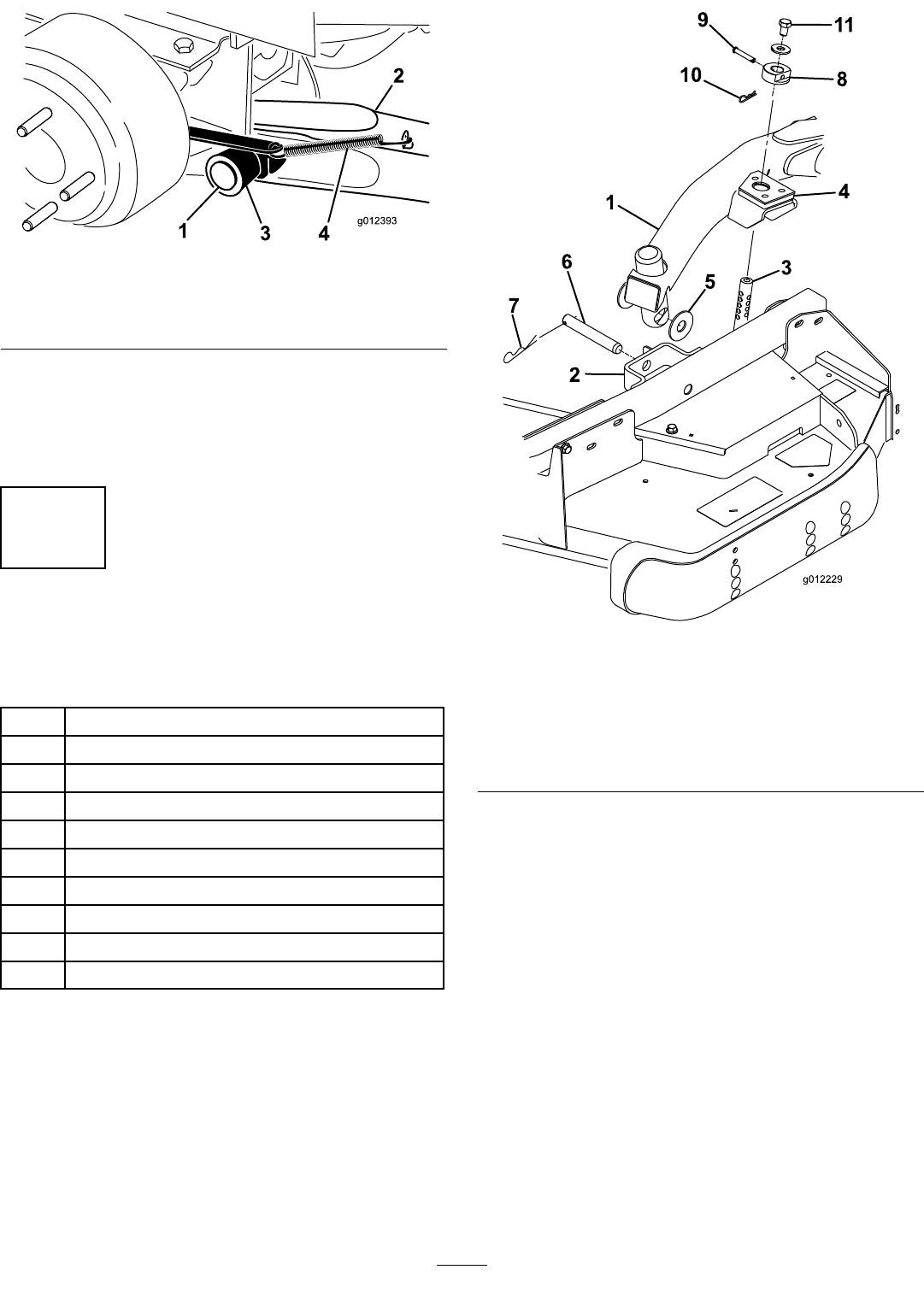
Figure3
1.Pivotpin4.Brakereturnspring
2.Liftarm
5.Tab
3.Pivotbracket
6.Installthewheelandtireassembly.Torquethewheel
nutsto75–80ft-lb(102–108N-m).
7.Repeattheprocedureontheoppositesideofthe
machine.
3
ConnectingtheLiftArmsto
theCuttingUnit
Partsneededforthisprocedure:
1
Liftarm,right
1
Liftarm,left
4Thrustwasher-nylon
4
Clevispin
2Hairpin
2
Heightofcutcollar
2
Clevispin
2Hairpin
2
Capscrew,1/2x3/4inch
2Washer
Procedure
1.Movethecuttingunitintopositioninfrontofthe
tractionunit.
2.MovetheliftlevertotheFloatposition.Pushalift
armdownuntiltheholesintheliftarmlineupwith
theholesinthecastorarmbracketandtheheight
ofcutrodcanbeinsertedintotheliftarmpads
(
Figure4).
Figure4
1.Liftarm
7.Hairpincotter
2.Castorarmbracket8.Height-of-cutcollar
3.Height-of-cutrod9.Clevispin
4.Liftarmpads
10.Hairpincotter
5.Thrustwashers11.Bolt
6.Clevispin
3.Securetheliftarmtothecastorarmwith(2)thrust
washers,aclevispinandahairpincotter.Position
thethrustwashersbetweentheliftarmandthe
castorarmbracket(Figure4).Insertendofcotter
pinintotheslotinthecastorarmtabtoretaincotter
pin.
4.Repeattheprocedureontheoppositeliftarm.
5.Startthetractionunitandraisethecuttingunit.
6.Pushdownontherearofthecuttingunitandinsert
theheightofcutrodsthroughtheliftarmpads.
7.Installtheheightofcutcollarsontotheheightof
cutrodsandsecurewiththeclevispinsandhair
pincotters(Figure4).Headofclevispintobe
positionedtowardthefrontofthedeck.
8.Installa1/2x3/4inchboltandawashertotopof
eachheightofcutrod(Figure4).
10