
Operator's Manual


9
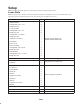
Setup
Note: Determine the left and right sides of the machine from the normal operating position.
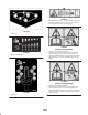
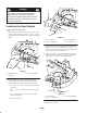
Loose Parts
Note: Use this chart as a checklist to ensure that all parts necessary for assembly have been received. Without these parts,
total setup cannot be completed. Some parts may have already been assembled at the factory.
Description
Qty. Use
Rubber deflector
Carriage bolt, 5/16 x 1– in.
Flange nut, 5/16
L.H. Foot shield
Carriage bolt, 5/16 x 1 in.
Flange nut, 5/16
Carriage bolt, 1/4 x 3/4 in.
Flange nut, 5/16
Capscrew, 1/4 x 3/4 in.
Flat washer
Lock nut, 1/4
R.H. Foot shield
Carriage bolt, 5/16 x 3/4 in.
Flange nut, 5/16
Rear deflector
Carriage bolt, 5/16 x 1–1/4 in.
Flange nut, 5/16
1
2
2
1
2
2
1
1
1
1
1
1
3
3
1
3
3
Mount to rear of cutting unit
(Models 30369 & 30367 only)
Castor wheel assembly 2 Mount to front of cutting unit
Pivot pin assembly
Cotter pin
2
2
Mount lift arms to traction unit
Lift arm R.H.
Lift arm L.H.
Thrust washer
Clevis pin
Hair pin
Height of cut collar
Clevis pin
Hair pin
Capscrew, 1/2 x 3/4 in.
Washer
1
1
4
4
2
2
2
2
2
2
Mount cutting unit to lift arms
EEC certificate 1
Parts Catalog 1
Operator’s manual 1 Read before operating the machine.