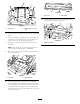
Form No. 3383-161 Rev A Polar Trac Kit Groundsmaster® 7200 Series Mower Model No. 30370—Serial No. 314000001 and Up Register at www.Toro.com.
This product complies with all relevant European directives, for details please see the separate product specific Declaration of Conformity (DOC) sheet. Model No. Serial No. WARNING This manual identifies potential hazards and has safety messages identified by the safety alert symbol (Figure 2), which signals a hazard that may cause serious injury or death if you do not follow the recommended precautions.
Contents Safety Introduction .................................................................. 2 Safety ........................................................................... 3 Safe Operating Practices........................................... 3 Safety and Instructional Decals ................................. 5 Setup ............................................................................ 6 1 Install Heat Shields................................................
• Replace faulty silencers/mufflers. • Before using, always visually inspect to see that the attachments are not worn or damaged. Replace worn or damaged components. • Safe Handling of Fuels • To avoid personal injury or property damage, use • • • • • • • • • • • extreme care in handling gasoline. Gasoline is extremely flammable and the vapors are explosive. Extinguish all cigarettes, cigars, pipes, and other sources of ignition. Use only an approved fuel container.
• Do not operate near drop-offs, ditches, steep banks or • Allow the engine to cool before storing in any enclosure. water. Tracks dropping over edges can cause roll overs, which may result in serious injury, death or drowning. • To reduce the fire hazard, keep the engine, silencer/muffler, battery compartment and fuel storage area free of grass, leaves, or excessive grease. • Do not operate on slopes where slippery conditions could reduce traction and could cause sliding and loss of control.
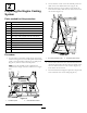
Setup Loose Parts Use the chart below to verify that all parts have been shipped. Procedure 1 2 3 4 5 Description Qty.
Procedure 6 7 8 9 11 Description Qty.
Note: The heat shield material must be affixed so that the rear panel can be reinstalled to the frame without pinching the heat shield material. 1 Install Heat Shields Parts needed for this procedure: 1 Heat shield-rear panel (supplied with cab model 30371) 1 Heat shield-front cover (supplied with cab model 30371) 1 Heat shield-seat (supplied with cab model 30371) 1 Heat shield-seat (supplied with kit) 1 Heat shield-seat 2 x 10 inch (supplied with cab model 30371) 3 Rubber grommet Figure 4 1.
Figure 8 1. Front cover 2. Heat shield 14. Install rubber grommets into the 3 holes in the rear frame mount as shown in (Figure 9). Figure 6 1. Heat shield 2. Heat shield 2 x 10 inch piece 9. Insert the seat wire harness through the slit in the heat shield. 10. Remove the backing and affix the 2 x 10 inch piece of self-adhesive heat shield between the seat latches on the bottom of the seat mount plate (Figure 6). Figure 9 1. Rubber grommets 11.
2. On the left rear corner of the cab assembly, locate the label on the hose marked “Pressure” (Figure 10). 2 3. Measure down 43.1 cm (17 inches) from where the hose exits the frame, mark the hose and cut the hose at this location (Figure 11).
Figure 14 1. Rear frame mount Figure 12 1. Return hose 4. Quick disconnect coupler 2. Pressure hose 5. Nipple coupler 9. Install the bulkhead bracket to the left rear frame mount with 2 self-tapping screws (5/16 inch) (Figure 15). 3. Hose clamps 6. Insert the barb end of a quick disconnect coupler into the return hose and secure with a hose clamp (Figure 12). 7. From the remaining piece of hose cut 2 lengths of hose, 140 cm (55 inches) and 57 cm (22–1/2 inches) (Figure 13).
Figure 18 Figure 16 1. Quick disconnect coupler 3. Nipple coupler 2. Dust plug 4. Dust cap 1. Radiator hose 3. 132 cm (52 inch) long hose 2. Tee fitting 15. Connect the 140 cm (55 inch) length of previously cut hose to the new tee fitting in the radiator hose (Figure 18). Secure the hose to the tee fitting with a hose clamp.
Figure 20 1. 57 cm (22–1/2 inch) hose 3. Cable tie 2. 132 cm (52 inch) Hose Figure 22 16. Disconnect the wire and remove the thermo-switch from the left side of the engine thermostat housing (Figure 21). Discard the switch. 1. Engine thermostat housing 3. 57 cm (22–1/2 inch) long hose 4. Hose clamp 2. Hose adapter fitting 18. Connect the 57 cm (22–1/2 inch) length of hose to the engine thermostat housing adapter fitting (Figure 22). Secure the hose to the adapter fitting with a hose clamp.
Figure 25 1. Rear frame mount 2. Grommet Figure 24 1. Dual contact switch 3. Harness connector 4. Connector cap 2. Wire from old left switch 2. Unlatch the control panel cover and lay it to the side (Figure 26). 21. Secure the wire, previously connected to the right side switch, to the male spade terminal. 22. Connect the wire, previously connected to the left side switch, to the lead on the new switch.
7. Insert the fusible link connector through the rubber boot on the positive battery cable. 8. Connect the fusible link to the positive battery post (Figure 29). 9. Connect the black wire to the negative battery post (Figure 29). Figure 27 1. Harness 3. Long cab wire (orange) 2. Harness wire clips 4. Cable tie 4. Inside the control panel, locate the pink wire with the connector enclosed in a plastic bubble (Figure 28).
5 Removing the Mower Deck Parts needed for this procedure: Figure 30 1. Rear bumper tube 2. Floor jack 2. Install the skid plate (Figure 31) to the frame below the engine as follows: A. Mount the front of the skid plate to the skid mounting plate with 2 flange-head bolts (3/8 x 1-3/4 inches) and flange nuts (3/8 inch) (Figure 31). B. 2 Vertical tube support assembly 1 Conversion bracket, L.H. 1 Conversion bracket, R.H.
1 2 3 4 Figure 35 G024844 Figure 33 1. Floor plate 1. Deck frame 3. Clevis pin 2. Self-tapping screw 4. Vertical tube support assembly 6. Loosen the PTO drive shaft bolts and nuts. Remove the roll pin and pull the drive shaft off of the gearbox shaft (Figure 36). 3.
Figure 37 1. Deck lift cylinder 3. Screw 2. Retaining ring 4. Cylinder pin Figure 39 1. Control valve 2. Tank hose 3. Pressure hose 11. Disconnect the pressure hose from the control valve (Figure 39). Install the cap from the winter kit valve into the control valve fitting and plug the hose with the plug supplied. 8. Remove the screw securing the front cylinder pivot pin to the mower frame (Figure 37). Remove the cable tie securing the pressure and tank hoses. 9.
Figure 41 1. Two mounting bolts (3/4 inch), washers and nuts (Right side) 14. Pull mower deck and frame from traction unit and roll forward out of the way. Figure 42 1. 2 x 4 6 2. On the traction unit, install hose covers onto the loose hydraulic pressure and tank hoses and secure with 2 cable ties each. Installing the Winter Frame Assembly 3. Loosen the pressure hose fitting at the pump and rotate the fitting 45 degrees toward the front of the machine (Figure 43).
G016166 Figure 44 1. Floor plate cover 2. Mounting screws Figure 46 5. Carefully roll the winter frame assembly into position while routing the drive shaft through the frame tube (Figure 45). 1. Tank hose 2. Pressure hose 7. Connect the drive shaft to the gear box shaft in the winter frame and torque the bolts (5/16 inch) to 20 to 25 N-m (175-225 in-lb). Install the roll pin (Figure 47). 4 2, 3 Figure 45 1. Drive shaft 2. Frame tube 6.
Figure 50 Figure 48 1. 3/4 inch bolts 1. Summer drive tire 2. Coupler pin Note: The rear tires will need to be removed to torque the rear bolts (3/4 inch). After torquing the frame bolts, install the rear tires and torque lug nuts to 88 to 115 N-m (65 to 85 ft-lb). 9. Adjust the floor jack to line up the 1.00 inch holes in the frame and install a coupler pin on each side (Figure 49). 11. Connect the hydraulic pressure hose to the valve hard line and tank hose to the valve (Figure 51).
Figure 54 1. Front tire 18. Remove the 2 x 4 from between the frame and the front bogie stop. Figure 52 19. Carefully lift the tracks over the rear wheel and front hubs. The direction of the track rotation is printed on the track. The V design in the rubber track must point forward. 1. Access covers 15. Remove the flat washer (1/2 inch) and nut (1/2 inch) installed on the stud on each bogie pivot (Figure 53). CAUTION The track guides have many pinch points.
7 Installing the Cab Mount Supports Parts needed for this procedure: Figure 56 22. Lower the floor jack until the front wheels support the frame. Install the flat washers (1/2 inch) and locknuts on the bogie pivot stud (Figure 56) and torque to 102 N-m (75 ft-lb). Note: You may need to move the floor jack to the rear bumper to raise the rear of the machine high enough to install the flat washer and locknut. 23. Re-install the side access covers with the screws previously removed (Figure 57).
2. Align the corner mat mounting holes with the bottom holes in the rear panel and the lower frame cross member holes (Figure 61). Secure the corner mats to the rear panel and cross member with 2 rear panel mounting screws previously removed. Use the remaining screw to secure the bottom middle of the rear panel to the cross member. Figure 59 1. ROPS post 3. Top plate hole 2. Cab mount support Figure 61 1. Seal (2) 3. Rear panel 2. Corner mat (2) 8 3. Clean the right and left edges of the rear panel.
Figure 64 1. Cab door bracket 3. Clip 2. Door closer Note: The cab doors and windows may be removed to ease installation, decrease the lifting weight and to prevent possible damage. Figure 63 1. Front cover 2. Remove the fasteners securing the cab to the shipping pallet. 9 3. Insert a rubber cab mount at the front and rear mounting locations (Figure 65). 4. Using a suitable overhead hoist, carefully lift the cab into position on the machine.
G009487 2 1 1 Figure 67 3 1. Return hose Figure 66 1. Bolt 3. Power point shield 2. Pressure hose 3. Remove the cap and plug the cab wire harness connector into the harness on the rear frame mount (Figure 68). 2. Power point assembly 7. Slide the power point shield up over power point while aligning the shield hole with the hole in the power point assembly plate (Figure 66). The longer end of the shield is to point forward to protect the power point. 8.
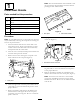
Product Overview 7. Start the machine. Run the lift arm up and down and check for hydraulic leaks. Check the hydraulic fluid and radiator levels and replenish as required. 11 Reading the Manuals Parts needed for this procedure: 1 Operator's Manual 1 Parts Catalog 1 Pre-delivery Inspection Sheet 1 Certificate of Quality 1 Jacking tube 2 Jacking tube bolts 1. Track 2. Front lift arm 5. Door latch 6. Fuel tank cap 1 Eyelet 3. Windshield wiper 7. Hood 1 Spacer 4.
Operation Make sure hydraulic quick couplers are free of any contaminates before connecting. Note: Determine the left and right sides of the machine from the normal operating position. Keep output shaft oiled to prevent rust. Never operate the PTO with attachment in the raised position. Noise from the PTO drive line will be evident. Think Safety First Install the attachment as follows: Please read all safety instructions and symbols in the safety section.
Figure 74 1. Floor plate cover 2. Mounting screws Figure 72 1. .281 inch diameter hole location (Between pedals) 4. Remove the roll pin and loosen the two capscrews securing the drive shaft to the gearbox shaft (Figure 75). Slide the drive shaft off the gearbox shaft. 2. From the front of the cab, install the eyelet and spacer to the cab wall with a flange nut (Figure 73). 4 2, 3 Figure 73 1. Eyelet 3. Hole in cab wall 2. Spacer 4. Flange nut 6 G016205 5 1 3.
12. Raise the floor jack high enough so that the track can be slid off of the front tire. CAUTION The track guides have many pinch points. Carefully grasp the rubber track on the outer edges outboard of the steel guides when moving the track. 13. Repeat the procedure on the other side of the machine. Move the tracks away from the machine. 14. Place an additional jack stand under front of machine. Place a drain pan under the control valve. 15.
Figure 81 1. 3/4 inch bolts Figure 79 1. Cab wire harness connector 2. Coupler pin 20. Install the summer drive tires with two nuts per tire (Figure 82). 2. Harness connector on the rear frame mount 18. Disconnect the pressure and return quick coupler hoses from the cab (Figure 80). Plug the couplers into each other to keep clean. Install the cap and dust covers onto the quick couplers on the machine. Make sure all connectors are clean before making connections. Figure 82 1. Summer drive tire 21.
little at a time. Alternate frequently from side to side so that the bolts support the cab evenly and stay in position in the holes in the floor plate. Figure 83 1. Jacking bolts 2. Cab jack tube Figure 85 1. Jacking bolts 23. Remove the front jack stand and lower the front of the machine onto the tires. 28. Remove the front jack stand and lower the front of the machine onto the tires until the coupler pins (Figure 86) are loose enough to be removed. 24.
Note: Figure 87 is shown as viewed from under the traction unit. Figure 89 1. Floor plate 34. Slide the drive shaft onto the gearbox shaft (Figure 90). Install the roll pin and torque the bolts to 175-225 in-lb (20 to 25 N-m) . Figure 87 1. Pump 2. Pressure hosed fitting (rotated 45 degrees) 31. Roll the summer deck and frame into position and install the five 3/4 inch bolts, washers and nuts that connect the deck frame to the rear frame (Figure 88).
Figure 91 1. Control valve 2. Tank hose 3. Pressure hose 36. Install the rear of the deck lift cylinder onto the pivot pin and secure with the retaining ring (Figure 92). Figure 93 37. Secure the front of the lift cylinder to the mower frame with the cylinder pin and screw (Figure 92). 1. ROPS post 2. Cab mount support 39. Position the ROPS assembly onto the ROPS posts. Install the bolt, nut, hair pin cotter and pin securing each ROPS assembly to the ROPS posts (Figure 94). 1 4 2 3 Figure 92 1.
1 4 2 3 5 G004634 Figure 95 1. ROPS 2. Pin Figure 97 4. Bolt & nut 5. ROPS post 1. Rear bumper tube 2. Floor jack 3. Cotter pin 5. On traction units that have a serial number prior to 312999999, install the vertical tube support assembly to each rear corner of the deck frame with a clevis pin and a self-tapping screw, 1/4 inch (Figure 98). 3.
1 2 3 4 5 7 G024845 6 Figure 99 1. Deck frame 5. Self tapping screw 2. Flange nut 6. Vertical tube support assembly 3. Conversion bracket (left side shown) 7. Self tapping screw Figure 101 1. Deck lift cylinder 12. Pivot open the floor plate (Figure 102) and secure with prop rod. 4. Screw 7. Install the vertical tube support assembly to the conversion bracket (right or left hand) on each corner of the deck frame with a 3/8 x 2–1/4 inch screw and 3/8 inch flange nut (Figure 99). 8. 9.
Figure 105 1. 3 mounting bolts (3/4 inch), washers and nuts (Left side) Figure 103 1. Pressure hose 2. Tank hose 3. Hose cover 4. Cable tie 5. Bolts 6. Roll pin 14. Disconnect the tank hose from the control valve (Figure 104). Cap the hose and fitting with a cap and plug. Pull the tank hose back toward the rear of the frame. Figure 106 1. Two mounting bolts (3/4 inch), washers and nuts (Right side) 18. Roll the mower deck and frame forward and out of the way. 19.
Figure 109 1. Drive shaft 2. Frame tube Figure 107 1. Pump Note: If the rear of the cab is not high enough to clear the control handles, evenly tighten the jacking bolts on each side of the cab jack tube to raise the rear of the cab (Figure 110). 2. Pressure hosed fitting (rotated 45 degrees) 20. Remove the two screws securing the winter frame floor plate cover to the floor and remove the plate (Figure 108). Figure 110 1. Jacking bolts Figure 108 1. Floor plate cover 22.
Figure 113 1. Summer drive tire G016166 25. Adjust the floor jack to line up the 2.5 cm (1.00 inch) holes in the frame and install a coupler pin on each side (Figure 114). Figure 111 1. Tank hose 2. Pressure hose 23. Connect the drive shaft to the gear box shaft in the winter frame and torque the bolts (5/16 inch) to 20 to 25 N-m (175-225 in-lb). Install the roll pin (Figure 112). 4 2, 3 Figure 114 1. Coupler pin G016205 6 5 26.
Figure 115 1. 3/4 inch bolts 2. Coupler pin Note: The rear tires will need to be removed to torque the rear bolts (3/4 inch). After torquing the frame bolts, install the rear tires and torque lug nuts to 88 to 115 N-m (65 to 85 ft-lb). Figure 117 1. Jacking bolts 2. Cab jack tube 29. At the rear mounting points, secure the cab to the machine with a bolt (1/2 x 3 inches), steel washer (1/2 x 2–1/2 inches), rubber washer (1/2 x 2–1/2 inches) and nut (1/2 inch) (Figure 118).
1 2 G009488 Figure 121 1. Pressure hose 2. Tank hose Figure 119 1. Cab mount 2. ROPS post 33. Raise the rear of the machine until 2 jack stands can be positioned under the rear tube at a height that supports the rear tires 1 to 3 inches (2.5 to 7.5 cm) off of the ground. 3. Bolts & nuts 4. ROPS post 31. Loosen the jacking bolts and remove the cab jack tube from the cutouts in the cab floor (Figure 120). 34. Lower the floor jack so the rear frame rests on the jack stands.
Figure 125 Figure 123 1. Front tire 41. Lower the floor jack until the front wheels support the frame. Install the flat washers (1/2 inch) and locknuts on the bogie pivot stud (Figure 125) and torque to 102 N⋅m (75 ft-lb). 38. Carefully lift the tracks over the rear wheel and front hubs. The direction of the track rotation is printed on the track. The V design in the rubber track must point forward.
Figure 127 1. Floor plate cover Figure 129 2. Mounting screws 1. Cab wire harness connector 44. Connect the cab pressure and return hoses to the quick couplers on the rear frame mount (Figure 128). 2. Harness connector on the rear frame mount 46. Start the machine. Run the lift arm up and down and check for hydraulic leaks. Check the antifreeze level and replenish as required. Figure 128 1. Pressure hose 2. Return hose 45.
Maintenance Recommended Maintenance Schedule(s) Maintenance Service Interval Maintenance Procedure After the first 10 hours • Torque the frame mounting bolts. • Torque wheel lug nuts. Every 50 hours • Lubricate grease fittings • Check the tire pressure. Every 200 hours • Torque wheel lug nuts. CAUTION If you leave the key in the ignition switch, someone could accidently start the engine and seriously injure you or other bystanders. Remove the key from the ignition before you do any maintenance.
Electrical System Maintenance Important: Whenever working with the electrical system, always disconnect the battery cables, negative (-) cable first, to prevent possible wiring damage from short-outs. Checking the Fuses Refer to the Operator's Manual supplied with the cab for instructions on fuses. If the machine has any electrical system issues, check the fuses. Grasp each fuse and remove them one at a time, checking to see if any are blown.
Drive System Maintenance 3. Loosen and remove the locknut and flat washer from the bogie pivot weldment (Figure 134). Checking the Tire Pressure Service Interval: Every 50 hours Check the tire pressure every 50 hours (Figure 132). Maintain the air pressure in the tires at 240 kPa (35 psi). Uneven tire pressure can cause lose of traction. If a lose of traction occurs, tire pressure may be increased to 344 kPa (50 psi) to increase track tension.
Storage Machine 1. Thoroughly clean the machine and cab, paying special attention to these areas: • PTO shaft assembly • All grease fittings and pivot points • Oil the spline on the PTO output shaft to prevent rusting 2. Check and adjust tire pressure; refer to Checking Tire Pressure. 3. Check all fasteners for looseness and tighten them as necessary. Especially torque the 5 bolts securing the winter frame to the traction unit to 359 N⋅m (265 ft-lb). 4. Grease or oil all grease fittings and pivot points.
The Toro Total Coverage Guarantee A Limited Warranty Conditions and Products Covered The Toro Company and its affiliate, Toro Warranty Company, pursuant to an agreement between them, jointly warrant your Toro Commercial product (“Product”) to be free from defects in materials or workmanship for two years or 1500 operational hours*, whichever occurs first. This warranty is applicable to all products with the exception of Aerators (refer to separate warranty statements for these products).