
Operator's Manual
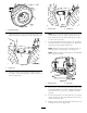
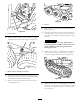
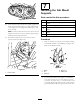
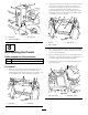
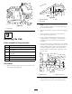
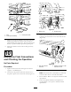
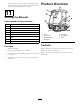
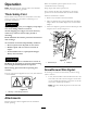
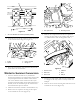
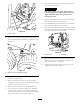

Figure48
1.Summerdrivetire
9.Adjusttheoorjacktolineupthe1.00inchholesinthe
frameandinstallacouplerpinoneachside(Figure49).
Figure49
1.Couplerpin
10.Adjusttheoorjackasrequiredtoinstallthebolts
(3/4inch)oneachside(Figure50).Torquetheboltsto
359N-m(265ft-lb).
Figure50
1.3/4inchbolts2.Couplerpin
Note:Thereartireswillneedtoberemovedtotorque
therearbolts(3/4inch).Aftertorquingtheframe
bolts,installthereartiresandtorquelugnutsto88to
115N-m(65to85ft-lb).
11.Connectthehydraulicpressurehosetothevalvehard
lineandtankhosetothevalve(Figure51).Retainthe
hoseplugsforthesummerchangeover.
Note:Makesurethehosesarenotkinkedorarenot
rubbingagainstanysharpedgesormovingparts.
Note:Adjusttheangleofthettingstoaccommodate
theroutingofthehoses.
G009488
1
2
Figure51
1.Pressurehose2.Tankhose
12.Raisetherearofthemachineuntil2jackstandscanbe
positionedunderthereartubeataheightthatsupports
thereartires2.5to7.5cm(1to3inches)offofthe
ground.
13.Lowertheoorjacksotherearframerestsonthejack
stands.Positiontheoorjackunderthecenterofthe
frontliftarmpivottube.
14.Removethetwoscrewssecuringeachsideaccesscover
andremovethecovers(
Figure52).
21