
Operator's Manual
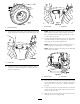
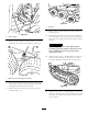
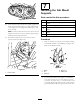
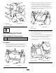
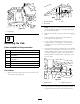
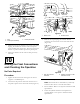
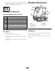
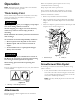
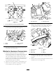
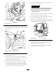

Figure56
22.Lowertheoorjackuntilthefrontwheelssupportthe
frame.Installtheatwashers(1/2inch)andlocknuts
onthebogiepivotstud(Figure56)andtorqueto102
N-m(75ft-lb).
Note:Youmayneedtomovetheoorjacktotherear
bumpertoraisetherearofthemachinehighenoughto
installtheatwasherandlocknut.
23.Re-installthesideaccesscoverswiththescrews
previouslyremoved(Figure57).
Figure57
1.Accesscovers
7
InstallingtheCabMount
Supports
Partsneededforthisprocedure:
2
Cabmountsupport(suppliedwithcabmodel30371)
2
Bolt(1/2x3–1/2inches)(suppliedwithcabmodel
30371)
2
Nut(1/2inch)(suppliedwithcabmodel30371)
2
Bolt(3/4x3–1/2inches)(suppliedwithcabmodel
30371)
2
Lockwasher(3/4inch)(suppliedwithcabmodel
30371)
2
Nut(3/4inch)(suppliedwithcabmodel30371)
Procedure
1.Removethebolt,nut,hairpincotterandpinsecuring
eachROPSassemblytotheROPSposts(Figure58).
RemovetheROPSassembly.
G004634
1
2
3
4
5
Figure58
1.ROPS4.Bolt&nut
2.Pin
5.ROPSpost
3.Cotterpin
2.LooselyinstallacabmountsupporttoeachROPS
postwithtwobolts(1/2x3–1/2inches),twonuts
(1/2inch),twobolts(3/4x3–1/2inch)andtwonuts
(3/4inch)(Figure59).Makesurethetopplateholeis
positionedforward.Donottightenboltsatthistime.
23